
User Instructions
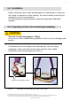
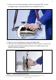
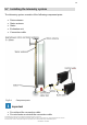
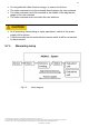
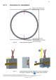
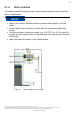
Table Of Contents
- 1 Safety Instructions
- 2 Markings used
- 3 Application
- 4 Structure and mode of operation
- 5 Mechanical installation
- 5.1 Important precautions during installation
- 5.2 Conditions on site
- 5.3 Installation orientation
- 5.4 Installation
- 5.5 Preparing for the rotor mounting (exemplary)
- 5.6 Mounting the rotor
- 5.7 Installing the telemetry system
- 5.7.1 Measuring setup
- 5.7.2 Instruction for installation
- 5.7.3 Calibration signal
- 5.7.4 Stator antenna
- 5.7.5 Evaluation unit
- 6 Electrical connection
- 7 Shunt signal
- 7 Functional testing
- 8 Maintenance
- 9 Dimensions of the stator antenna
- 10 Dimensions of the rotor antenna
- 11 Specifications

9
Geschäftsführung: Thomas Lippok & Jens Wiegand • Aufsichtsratsvorsitzender: Joseph Vorih
Sitz der Gesellschaft: Darmstadt • Als Gesellschaft mit beschränkter Haftung eingetragen im Handelsregister des Amtsgerichts Darmstadt unter HRB 1147
Unser Unternehmen ist bei der Stiftung Elektro-Altgeräte Register (EAR) unter der Nummer WEEE-Reg.-Nr. DE66485129 registriert.
CONFIDENTIAL - EXTERNAL
4. Clean the plane surfaces of the transducer flange and the counter flange.
For safe torque transfer, the faces must be clean and free from grease.
Use a piece of cloth or paper soaked in solvent. Make sure that no solvent
drips into the inside of the transducer and that the transmitter coils are not
damaged during cleaning.
5. Fasten the lifting equipment to the mounting eye bolt(s).
6. Carefully lift up the rotor and move it to the mounting position (see Fig 5.1).
5.6 Mounting the rotor
1. Prior to installation, clean the plane faces of the transducer flange
and the counter flange.
For safe torque transfer, the faces must be clean and free from grease.
Use a piece of cloth or paper soaked in solvent. When cleaning, make
sure that you do not damage the transmitter winding.
Important
If alternating loads are expected, use thread locker (medium strength,
e.g. LOCTITE No. 242) to glue the screws into the counter thread to
exclude loss of tightening stress due to screw slackening.
3. Fasten all screws with the specified torque.
4. Now remove the ring bolts and mounting ring(s).
Important
Keep them in a safe place for future dismounting.