
User Instructions
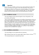
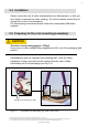
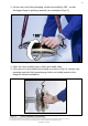
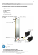
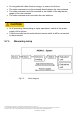
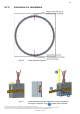
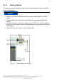
Table Of Contents
- 1 Safety Instructions
- 2 Markings used
- 3 Application
- 4 Structure and mode of operation
- 5 Mechanical installation
- 5.1 Important precautions during installation
- 5.2 Conditions on site
- 5.3 Installation orientation
- 5.4 Installation
- 5.5 Preparing for the rotor mounting (exemplary)
- 5.6 Mounting the rotor
- 5.7 Installing the telemetry system
- 5.7.1 Measuring setup
- 5.7.2 Instruction for installation
- 5.7.3 Calibration signal
- 5.7.4 Stator antenna
- 5.7.5 Evaluation unit
- 6 Electrical connection
- 7 Shunt signal
- 7 Functional testing
- 8 Maintenance
- 9 Dimensions of the stator antenna
- 10 Dimensions of the rotor antenna
- 11 Specifications

6
Geschäftsführung: Thomas Lippok & Jens Wiegand • Aufsichtsratsvorsitzender: Joseph Vorih
Sitz der Gesellschaft: Darmstadt • Als Gesellschaft mit beschränkter Haftung eingetragen im Handelsregister des Amtsgerichts Darmstadt unter HRB 1147
Unser Unternehmen ist bei der Stiftung Elektro-Altgeräte Register (EAR) unter der Nummer WEEE-Reg.-Nr. DE66485129 registriert.
CONFIDENTIAL - EXTERNAL
Important
Even if the unit is installed correctly, the zero point adjustment made at the
factory can shift by up to approx. 0.5% of the sensitivity. If this value is
exceeded, we advise you to check the mounting conditions. If the residual
zero offset when the unit is removed is greater than 1% of the sensitivity,
please send the transducer back to the Darmstadt factory for testing.
5.2 Conditions on site
The torque flange must be protected against coarse dirt particles, dust,
oil, solvents and humidity.
There is wide ranging compensation for the effects of temperature on the out-
put and zero signals of the transducer (see “Specifications" section). If there
are no static temperature ratios, for example, because of the temperature
differences between the measuring body and the flange, the values given in
the specifications can be exceeded. In this case, ensure static temperature
ratios by cooling or heating, depending on the application. As an alternative,
check if thermal decoupling is possible, e.g. by means of heat radiating
elements such as multiple disc couplings.
5.3 Installation orientation
The torque flange can be installed with any orientation.
With clockwise torque load, the output signal is from 10 kHz to 15 kHz
/ 0V to
10V corresponding zero to nominal torque load.