
User Instructions
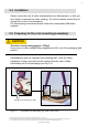
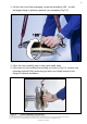
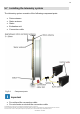
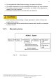
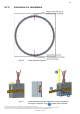
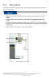
Table Of Contents
- 1 Safety Instructions
- 2 Markings used
- 3 Application
- 4 Structure and mode of operation
- 5 Mechanical installation
- 5.1 Important precautions during installation
- 5.2 Conditions on site
- 5.3 Installation orientation
- 5.4 Installation
- 5.5 Preparing for the rotor mounting (exemplary)
- 5.6 Mounting the rotor
- 5.7 Installing the telemetry system
- 5.7.1 Measuring setup
- 5.7.2 Instruction for installation
- 5.7.3 Calibration signal
- 5.7.4 Stator antenna
- 5.7.5 Evaluation unit
- 6 Electrical connection
- 7 Shunt signal
- 7 Functional testing
- 8 Maintenance
- 9 Dimensions of the stator antenna
- 10 Dimensions of the rotor antenna
- 11 Specifications

5
Geschäftsführung: Thomas Lippok & Jens Wiegand • Aufsichtsratsvorsitzender: Joseph Vorih
Sitz der Gesellschaft: Darmstadt • Als Gesellschaft mit beschränkter Haftung eingetragen im Handelsregister des Amtsgerichts Darmstadt unter HRB 1147
Unser Unternehmen ist bei der Stiftung Elektro-Altgeräte Register (EAR) unter der Nummer WEEE-Reg.-Nr. DE66485129 registriert.
CONFIDENTIAL - EXTERNAL
5 Mechanical installation
5.1 Important precautions during installation
NOTE
A torque flange is a precision measurement element and therefore needs
careful handling. Dropping or knocking the transducer may cause permanent
damage. Make sure that the transducer cannot be overloaded, even while it is
being mounted.
• Handle the transducer with care.
• Check the effect of bending moments, critical rotational speeds and natural
torsional oscillations, to prevent the transducer being overloaded by
increases in resonance.
• Make sure that the transducer cannot be overloaded.
WARNING
There is a danger of the transducer breaking if it is overloaded. This can
cause danger for the operating personnel of the system in which the
transducer is installed.
Implement appropriate safety measures to avoid overloads and to protect
against resulting dangers.
• If alternating loads are expected, use thread locker (medium strength, e.g.
LOCTITE No. 242) to fix the screws into the threaded holes to exclude
loss of tightening stress due to screw slackening.
• Comply with the mounting dimensions to enable correct operation.
Under no circumstances should the permissible limits specified for bending
moments, lateral and longitudinal forces be exceeded. Due to the torque
flange's high torsional stiffness, dynamic shaft train changes are kept to a
minimum.