
Operator's Manual
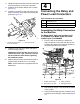

6.Installthe5Afuseintotheinlinefuseblockon
thepowerleadbranch.
5
RemovingtheExisting
Lever
NoPartsRequired
Procedure
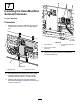
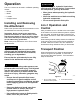
1.Removetheretainingringfromtheloader
arm/attachmenttiltlevershaftandmovethe
washerup(Figure20).
g242495
Figure20
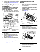
2.Pushuptheairdeectorfrombelowthecontrol
panelandslideitupthelever(Figure20).
Note:Youmayneedtoadjustthepositionof
thelevertoremovetheairdeector.
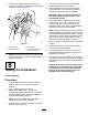
3.Loosenthelocknut(3/4inch)atthebaseofthe
lever(Figure21).
g242496
Figure21
Somepartsnotshownforclarity
4.Unscrewandremovetheleverandairdeector
(Figure21).
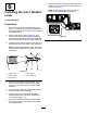
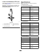
5.ModifytheairdeectorasshowninFigure22.
g242427
Figure22
1.Drilla5mmdiameterhole
fortheleverconnector
wire
4.Existinghole
2.Cuta30mmslotfromthe
centreofthedrilledhole
5.Slotsfacetowardlower
rightsideofcontrolpanel
3.10mmfromtheedgeof
theexistingholetothe
centreofthenewhole
13