
Operator's Manual

6
Installingthe4-in-1Bucket
Lever
NoPartsRequired
Procedure
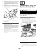
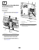
1.Ensurethattherockerswitchesatthetopof
the4-in-1bucketleverareatrightanglestothe
shaftopeningasshowninFigure23andtighten
thehandlelocknut.
2.Removetheinsertlocknut(Figure23)and
puttheleverthroughtheairdeectorwiththe
openingfacingforwardandthelevershaftlead
andconnectorfedthroughthesmalldrilledhole.
3.Installthelocknuttothebottomoftheleverand
threadtheleverintotheloadervalveassembly.
Note:Rotatetheairdeector,lever,andlever
connectorwirealtogethertomaintainthecorrect
orientation.
g242494
Figure23
1.Rockerswitch4.Insertlocknut
2.Handlelocknut
5.Levershaftlead
3.Shaftopening
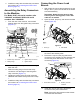
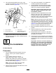
4.Withtheshaftopeningfacingforward,secure
theleverfromrotationandtightentheinsert
locknut(18mm)securelytotheloadervalve
assembly.
5.Loopthelevershaftleadclockwisearoundthe
topoftheloadervalveassembly.
6.Connecttheleverconnectortotheloader
arm/attachmentleverconnectorbeneaththe
controlpanel(Figure10).
7.Pushtheairdeectorbelowthecontrolpanel
andmovetheleverinalldirectionstoensure
thatitslidesfreely.
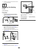
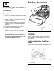
8.Attachthehandleinstructionaldecalontothe
bottomleftcornerofthecontrolpaneldecalas
showninFigure24.
Note:Cleanandpreparethecontrolpanel
decalbeforeinstallingthehandledecal.
g242493
Figure24
14