
Operator's Manual

4.Installthe2relaystothebucketrelayconnectors
andcontinuetoConnectingthePowerLead
Branch(page12).
AssemblingtheRelayConnectors
totheMachine
ForModel22327withserialnumbersafter
316000467andModel22328withserial
numbersafter316999999
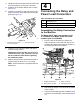
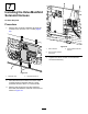
1.Fromtherearofthemachine,removeboth
existingrelaysfromtheignitionrelayconnectors
(Figure17).
g242426
Figure17
1.Bucketrelayconnectors3.Ignitionrelayconnectors
2.Matingtangs4.Ignitionrelays
2.Loosentheignitionrelayconnectormounting
boltsandnuts.
3.Slidethematingtangsofthebucketrelay
connectorsontothetangsoftheleftignition
relayconnector(Figure17).
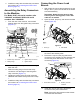
4.Tightentheignitionrelayconnectormounting
hardwareandinstalltherelaysremovedinstep
1.
5.Installthe2relaystothebucketrelayconnectors
andcontinuetoConnectingthePowerLead
Branch(page12).
ConnectingthePowerLead
Branch
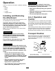
1.Withacabletie,securetheharnesstothehose
ttingintheT1portontheleftsideoftheloader
armvalveassembly.
Important:Routethewireharnessaway
fromanyhotormovingparts,securewith
cabletiesasneeded.
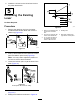
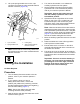
2.Openthehood,propitup,andremovetheheat
shield(Figure18).
g038212
Figure18
1.Screw(3)
2.Heatshield
3.Feedthepowerleadbranchforwardandaround
thefrontoftheauxiliaryvalve.
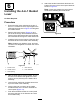
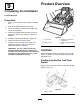
4.Removethecapfromtheplug-and-socket
connectorontheauxiliarylowowharnessand
connectthepowerleadbranchtotheopen
connector(Figure19).
g038242
Figure19
1.Powerleadconnector
2.Auxiliarylowow
connector
5.Installthecapintotheshort,taped-back
connectoronthepowerleadbranch.
Note:Securethewireharnesssothatitdoes
notcontacttheheatshield.
12