Form No. 3392-268 Rev B DH 210 Lawn Tractor Model No. 74585—Serial No. 315000001 and Up G017868 Register at www.Toro.com.
This product complies with all relevant European directives. For details, see the separate product specific Declaration of Conformity (DOC) sheet. Figure 2 1. Safety alert symbol Introduction This manual uses 2 other words to highlight information. Important calls attention to special mechanical information and Note emphasizes general information worthy of special attention. This rotary-blade, riding lawn mower is intended to be used by residential homeowners.
Contents Removing the Mower..............................................32 Installing the Mower ...............................................32 Storage ........................................................................33 Troubleshooting ...........................................................34 Schematics ...................................................................36 Safety ...........................................................................
Safety • Refuel outdoors only and do not smoke while refueling. • Add fuel before starting the engine. Never remove the cap of the fuel tank or add gasoline while the engine is running or when the engine is hot.
• Remember there is no such thing as a safe slope. Travel • • • • • • • • • • • • Disengage drive to attachments when transporting or not on grass slopes requires particular care. To guard against overturning: – do not stop or start suddenly when going up or downhill; – machine speeds should be kept low on slopes and during tight turns; – stay alert for humps and hollows and other hidden hazards; – never mow across the face of the slope, unless the lawn mower is designed for this purpose.
Toro Riding Mower Safety The following paragraph contains safety information specific to Toro products that is not included in the CEN standard. Use only Toro-approved attachments. The warranty may be voided if you use the machine with unapproved attachments. Sound Pressure This unit has a sound pressure level at the operator’s ear of 84 dBA, which includes an Uncertainty Value (K) of 1 dBA. The sound pressure level was determined according to the procedures outlined in EN ISO 5395:2013..
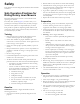
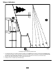
Slope Indicator G011841 Figure 3 This page may be copied for personal use. 1. The maximum slope you can safely operate the machine on is 10 degrees when mowing on side hills and 15 degrees when mowing uphill or downhill. Use the slope chart to determine the degree of slope of hills before operating. Do not operate this machine on a slope greater than 15 degrees. Fold along the appropriate line to match the recommended slope. 2. Align this edge with a vertical surface, a tree, building, fence pole, etc. 3.
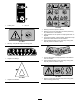
Safety and Instructional Decals Safety decals and instructions are easily visible to the operator and are located near any area of potential danger. Replace any decal that is damaged or lost. 104-3237 Manufacturer's Mark 1. Parking brake 1. Indicates the blade is identified as a part from the original machine manufacturer. 93-7276 1. Explosion hazard—wear eye protection. 2. Caustic liquid/chemical burn hazard—to perform first aid, flush with water. 3. Fire hazard—no fire, open flames, or smoking.
106-8552 2. Recycle 1. Collect grass 119-2725 1. Warning—read the Operator's Manual. 2. Warning—remove the spark plug wire before performing any maintenance on the machine. 3. Tipping hazard—do not operate on slopes greater than 10 degrees. 4. Thrown object hazard; crushing hazard, bystanders—keep bystanders a safe distance from the machine. 5. Cutting hazard of hand or foot—stay away moving parts, keep all guards and shields in place. 111–5941 1. Warning—keep hands away from moving parts.
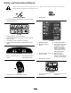
Product Overview Controls Become familiar with the controls (Figure 4) before you start the engine and operate the machine. 119-2730 1. Crushing/dismemberment hazard of bystanders—do not turn the key while children are present; keep children a safe distance from the machine. 2 1 3 4 5 6 7 8 9 G020501 Figure 4 1. Blade control (PTO) knob 2. Ignition switch 7. Forward speed pedal 3. Throttle and choke control lever 4. Brake pedal 8. Reverse speed pedal 5. Recycle-on-demand lever 10 6.
Specifications Weight Length Width 246 kg 260 cm 110 cm Operation Cutting Height width 102 cm 115 cm Engine Nominal speed engine power 2,600 rpm Note: Determine the left and right sides of the machine from the normal operating position. 10.17 Kw at 3,000 rpm Filling the Fuel Tank Recommended Fuel: • For best results, use only clean, fresh (less than 30 days old), unleaded gasoline with an octane rating of 87 or higher ((R+M)/2 rating method).
Using the Parking Brake of the filler neck. Do not fill the fuel tank completely full. Do not fill the fuel tank completely full. Always set the parking brake whenever you stop the machine or leave it unattended. Note: This space in the tank allows gasoline to expand. 4. Install the fuel tank cap securely. Setting the Parking Brake 5. Wipe up any gasoline that may have spilled. 1. Push the brake pedal (Figure 4) down and hold it.
1. Push and hold in the button on the height-of-cut lever (Figure 7). 1 G017870 Figure 7 1. Height-of-cut lever 2. Shift the height-of-cut lever to the desired position. 3. Release the button. Figure 6 1. Adjustment knobs Starting the Engine 1. Open the fuel shut-off valve located between the fuel tank and the engine (Figure 8). 2. Move the seat to the desired position and tighten the knobs. Operating the Headlights The headlights are an integral function of the ignition switch.
Note: If the engine has been working hard or is hot, let it idle for a minute before turning the ignition key to the Off position. This allows the engine to cool the engine before you stop it. You may stop the engine in an emergency by turning the ignition key to the Off position. 6. When starting a cold engine, push the throttle control lever fully forward to the choke position (Figure 9).
1 1 G017873 Figure 12 1. Operating-in-reverse light 4. Operate the machine in reverse and complete your task. 5. Disengage the blades (PTO) to activate the interlock. 6. Remove the KeyChoice key and put it in a safe place out of the reach of children. Testing the Safety Interlock System G017872 Figure 11 1. KeyChoice switch CAUTION If the safety interlock switches are disconnected or damaged, the machine could operate unexpectedly, causing personal injury. • Do not tamper with the interlock switches.
Driving the Machine Forward or Backward the engine, shift the blade control (PTO) knob into the Engage position, and turn the KeyChoice key and release it: The operating-in-reverse warning light should illuminate. 6. Shift the blade control (PTO) knob to the Disengage position: The operating-in-reverse warning light should turn off. The throttle control regulates the engine speed as measured in RPM (revolutions per minute). Place the throttle control in the Fast position for best performance.
2. Disengage the blades (PTO). 2. Disengage the blades (PTO) and move the throttle to the Slow position. 3. Turn the ignition key to the Off position. 3. Pull the grass collector dump lever forward and tilt the grass collector (Figure 16). 4. Set the parking brake if you leave the machine unattended; refer to Setting the Parking Brake. Note: Remove the keys from the ignition and KeyChoice switches.
1 1 G017883 G017876 Figure 19 Figure 17 1. Locking latch 1. Locking latch 2. Disengage the blades (PTO) and move the throttle to the Slow position. 4. Mow the grass with the grass collector in the open position as desired. 3. Pull the grass collector dump lever forward and tilt the grass collector (Figure 18) until the locking latch engages to lock the grass collector in the open position (Figure 19). 5.
Operating Tips • For the best performance, operate the engine at the maximum speed. The mower requires air to thoroughly cut grass clippings, so do not set the height-of-cut too low or completely surround the mower in uncut grass. Always leave one side of the mower free from uncut grass to allow the air to be drawn into the mower. • Cut the grass slightly longer than normal to ensure that the cutting height of the mower does not scalp any uneven ground.
Maintenance Note: Determine the left and right sides of the machine from the normal operating position. Recommended Maintenance Schedule(s) Maintenance Service Interval Maintenance Procedure After the first 5 hours • Change the engine oil. Before each use or daily • • • • • • Check the safety interlock system. Check the engine oil level. Check the battery electrolyte level. Check the brake. Check the blades. Clean the mower housing. Every 25 hours • Grease and lubricate the machine.
Lubrication 6. Connect a grease gun to each fitting and pump grease into it. Greasing and Lubricating the Machine 7. Wipe up any excess grease. Where to Add Grease Service Interval: Every 25 hours/Yearly (whichever comes first)—Grease and lubricate the machine. (Grease and lubricate it more frequently when operating it in dusty or sandy conditions.) How to Grease the Machine Note: Grease the machine with a general-purpose grease. 1. Disengage the blades (PTO). 2. Set the parking brake. 3.
Engine Maintenance Servicing the Air Cleaner Service Interval: Every 25 hours—Service the air cleaner foam element. (Service it more frequently when operating the machine in dusty or dirty conditions.) Every 100 hours—Service the air cleaner paper element. (Service it more frequently when operating the machine in dusty or dirty conditions.) 1. Park the machine on a level surface. 2. Disengage the blades (PTO). 3. Set the parking brake. 4. Stop the engine and wait for all moving parts to stop. Figure 23 5.
2. Align the tabs on the air cleaner cover with the slots of the blower housing (Figure 23). 3. Hook the handle onto the cover and press down on the handle to lock the cover in place. Servicing the Engine Oil Oil Type: Detergent oil (API service SF, SG, SH, SJ, or higher) Crankcase capacity: 47 oz. (1.4 l) with filter; 44 oz. (1.3 l) without filter Figure 25 Viscosity: See the oil table (Figure 24). 1. Dipstick 3. Filler tube 2. Metal end 4. Drain plug 8.
Servicing the Spark Plug 13. Check the engine oil level; refer to steps 9 and 10 of Checking the Engine Oil Level. Service Interval: Every 25 hours—Check the spark plug. Changing the Engine Oil Filter Every 100 hours—Replace the spark plug. 1. Drain the oil from the engine; refer to Changing the Engine Oil. Use a Champion RC12YC or equivalent spark plug. Ensure that the air gap between the center and side electrodes is 0.030 inch (0.76 mm) before installing the spark plug.
Fuel System Maintenance Draining the Fuel Tank Drain the fuel tank when you will not be using the machine for more than 30 days. Figure 28 1. Center electrode insulator DANGER 3. Air gap (not to scale) 2. Side electrode In certain conditions, gasoline and gasoline vapors are extremely flammable and highly explosive. A fire or explosion from gasoline can burn you and others and can damage property. • Drain gasoline from the fuel tank when the engine is cold. Do this outdoors in an open area.
Electrical System Maintenance Note: Now is the best time to install a new fuel filter because the fuel tank is empty. 10. Install the fuel line onto the fuel filter. 11. Slide the hose clamp close to the fuel filter to secure the fuel line (Figure 29). Replacing the Headlight Bulbs 1. Disengage the blades (PTO). Replacing the Fuel Filter 2. Set the parking brake. Service Interval: Every 100 hours/Yearly (whichever comes first) 3. Stop the engine and wait for all moving parts to stop. 4.
Replacing the Fuses 4. Remove the ignition key. The electrical system is protected by fuses. They are located beneath the hood, near the fuel tank (Figure 33). If a fuse goes out, check the circuit wiring for a short. 5. Lift up the seat to see the battery. 1 6. Lift the rubber cover up off the negative (black) cable. 7. Disconnect the negative (black) ground cable from the battery post (Figure 34). 2 G012460 Figure 33 1.
4. Using the bolt and wing nut, connect the negative (black) cable to the negative (–) battery post (Figure 34). Slide the rubber cover over the battery post. 4. Replace the filler caps. Charging the Battery Checking the Electrolyte Level WARNING Service Interval: Before each use or daily Charging the battery produces gasses that can explode. Never smoke near the battery and keep sparks and flames away from the battery. 1. Tip the seat forward to see the battery. 2. Look at the side of the battery.
Checking the Brake Drive System Maintenance Service Interval: Before each use or daily 1. Park the machine on a level surface. 2. Disengage the blades (PTO). Checking the Tire Pressure 3. Set the parking brake. Service Interval: Every 25 hours/Yearly (whichever comes first) 4. Stop the engine and wait for all moving parts to stop. 5. Remove the ignition key. Maintain the air pressure in the front tires at 15 psi (103 kPa) and rear tires at 12 psi (83 kPa).
Cleaning the Grass Collector and Tunnel Servicing the Grass Collector 1. Disengage the blades (PTO). 2. Set the parking brake. Removing the Grass Collector 3. Stop the engine and wait for all moving parts to stop. 1. Lock the locking latch on the grass collector (Figure 38). 4. Remove the ignition key. 5. Remove the grass collector; refer to Removing the Grass Collector. 1 6. Clean the collector bag with pressurized water. 7. Wipe the area around the full-bag sensor. 8.
Mower Deck Maintenance Removing the Blades 1. Remove the mower; refer to Removing the Mower. 2. Carefully tip the mower over. 3. Remove the bolts, washers, and blades (Figure 40). Wedge a block of wood between each blade and the mower to lock the blade when you are removing each bolt. Servicing the Blades Service Interval: Before each use or daily Note: Determine the left and right sides of the machine from the normal operating position. Note: The right blade has a left-hand threaded bolt. 4.
Important: The relief spring is very strong. Wedge the mower housing to ensure that it does not fly upward and cause damage. 11. Remove the pin between the front arm linkage and the mower housing (Figure 44). 12. Remove the V-belt from the engine pulley (Figure 44). 13. Slide the mower out from beneath the machine. Installing the Mower Reverse the procedure for Removing the Mower. Figure 43 3. Tighten the blade bolts to 37 ft-lb (50 N-m). Removing the Mower 1. Park the machine on a level surface. 2.
Storage 13. Remove and inspect the spark plug; refer to Servicing the Spark Plug. With the spark plug removed from the engine, pour 2 tablespoons of engine oil into the spark plug hole. Use the electric starter to crank the engine and distribute the oil inside the cylinder. Install the spark plug, but do not connect the wire to the spark plug. 1. Disengage the blades (PTO). 2. Set the parking brake. 3. Stop the engine and wait for all moving parts to stop. 4. Remove the ignition key. 14.
Troubleshooting Problem The starter does not crank. The engine overheats. The machine does not drive. The engine will not start, starts hard, or fails to keep running. Possible Cause 1. The blade control (PTO) knob is engaged. 1. Move the blade control (PTO) knob to the Disengaged position. 2. The parking brake is not on. 3. The battery is dead. 4. The electrical connections are corroded or loose. 5. A fuse is blown. 6. A relay or switch is damaged. 2. Set the parking brake. 3. Charge the battery. 4.
Problem There is abnormal vibration. The blades do not rotate. The cutting height is uneven. Possible Cause Corrective Action 1. The blades are bent or unbalanced. 1. Install a new blades. 2. The blade mounting screws are loose. 3. The engine mounting bolts are loose. 4. There is a loose engine pulley, idler pulley, or blade pulley. 5. The engine pulley is damaged. 6. The blade drive belt is damaged. 2. Tighten the blade mounting screws. 3. Tighten the engine mounting bolts. 4.
Schematics ELECTRO-MAGNETIC CLUTCH (Rev.
Notes: 37
Notes: 38
International Distributor List Distributor: Country: Phone Number: Distributor: Phone Number: 57 1 236 4079 Colombia Japan 81 3 3252 2285 Czech Republic 420 255 704 220 420 255 704 Slovakia 220 Argentina 54 11 4 821 9999 Russia 7 495 411 61 20 Ecuador 593 4 239 6970 Finland 358 987 00733 Agrolanc Kft Balama Prima Engineering Equip. B-Ray Corporation Hungary Hong Kong Korea 36 27 539 640 852 2155 2163 82 32 551 2076 Maquiver S.A. Maruyama Mfg. Co. Inc. Mountfield a.s.
Residential Products The Toro Warranty and The Toro GTS Starting Guarantee Conditions and Products Covered Owner Responsibilities The Toro Company and its affiliate, Toro Warranty Company, pursuant to an agreement between them, jointly promise to repair for the original purchaser1the Toro Product listed below if defective in materials or workmanship or if the Toro GTS (Guaranteed to Start) engine will not start on the first or second pull, provided the routine maintenance required in the Operator's Manua