
Operation Manual


B
B
2
1
3
g016532
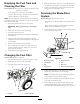
Figure37
1.Frontofcuttingdeck3.Measureformthecutting
edgetoasmooth,level
suface
2.MeasureatlocationsA
andB
2.Measurefromalevelsurfacetothecuttingedges
atlocationsAandB,(Figure37),andrecordboth
dimensions.
3.Rotatethebladessothattheiroppositeendsareat
locationsAandB.
4.Repeatthemeasurementsinstep2andrecordthem.
Note:IfthedifferencebetweenthedimensionsAand
Bobtainedinsteps2and4exceeds3mm(1/8inch),
replacetheblades;refertoRemovingtheBlades(page
23)andInstallingtheBlades(page23).
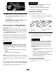
RemovingtheBlades
Replacethebladeswhentheystrikeasolidobject,areoutof
balance,bent,orworn.UseonlygenuineTororeplacement
blades.
1.Useablockofwoodtoholdeachbladesteadyandturn
thebladeboltcounterclockwiseasshowninFigure38.
Figure38
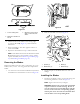
2.RemoveeachbladeasshowninFigure39.
G016530
1
2
3
4
Figure39
1.Spindle(2)3.Blade(2)
2.Bladedriver(2)4.Bladebolt(2)
3.Inspectthepinsonthebladedriversforwearand
damage.
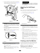
InstallingtheBlades
1.Installtherstbladesothatitishorizontal,alongwith
allmountinghardwareasshowninFigure39.
Note:Tightentheboltwithyourngers.
Important:Positionthecurvedendsoftheblades
topointtowardthemachinehousing.Besureto
nesttheraisedareasoneachbladedriverwiththe
recessesintheheadofitscorrespondingspindle,
andthepinsontheothersideofeachbladedriver
withtheholesinitscorrespondingblade.
23