
Operator's Manual
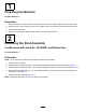
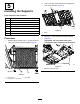
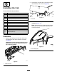

4.Liftthecabframeusingtheliftpointsandplace
itonthemachine(Figure11).
g037103
Figure11
1.Liftpoints
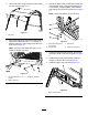
5.Securethesidesofthecabframetothemachine
using6hex-headbolts(3/8x1-1/4inches),6
washers(3/8inch),and6angenuts(3/8inch)
asshowninFigure12.
Note:Torquethehex-headbolts(3/8x1-1/4
inches)to58N∙m(43ft-lb).
g037137
Figure12
1.Hex-headbolt(3/8x1-1/4
inches)
3.Flangenut(3/8inch)
2.Washer(3/8inch)
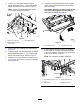
6.Securethebackofthecabframetotheleftand
rightsupportsusing4ange-headbolts(5/16x
1-1/4inches),2supportplates,4atwashers,
and4angenuts(5/16inch)asshowninFigure
13.
Note:Torquetheboltsto34N∙m(25ft-lb).
g035253
Figure13
1.Flange-headbolt(5/16x
1-1/4inches)
3.Flatwasher
2.Supportplate4.Flangenut(5/16inch)
7.Tightentheleftandrightsupports,andtorque
theboltsto58N∙m(43ft-lb)asshowninFigure
7.
8.Installthepreviouslyremovedlefthandhold
usingthe3screwsand3nuts(Figure9).
9.Installtheupper,rearfoamseal(Figure14).
g038338
Figure14
1.Upper,rearfoamseal
10