Form No. 3451-132 Rev A Workman® GTX EFI Utility Vehicle Model No. 07059LT—Serial No. 410500000 and Up Register at www.Toro.com.
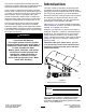
Introduction This product complies with all relevant European directives; for details, please see the separate product specific Declaration of Conformity (DOC) sheet. This utility vehicle is intended to be primarily used off-highway to transport people and material loads. Using this product for purposes other than its intended use could prove dangerous to you and bystanders.
The safety-alert symbol (Figure 2) appears both in this manual and on the machine to identify important safety messages that you must follow to avoid accidents. This symbol will appear with the word Danger, Warning, or Caution. • Danger indicates an imminently hazardous situation which, if not avoided, will result in death or serious injury. • Warning indicates a potentially hazardous situation which, if not avoided, could result in death or serious injury.
Contents Servicing the Engine Oil.................................... 38 Servicing the Spark Plug................................... 39 Adjusting the High/Low Idle .............................. 40 Fuel System Maintenance ................................... 40 Inspecting Fuel Lines and Connections............. 40 Replacing the Fuel Filter ................................... 40 Servicing the Carbon Canister .......................... 41 Electrical System Maintenance ...........................
Safety This machine has been designed in accordance with the requirements of SAE J2258 (Nov 2016). General Safety This product is capable of causing personal injury. Always follow all safety instructions to avoid serious personal injury. • Read and understand the contents of this Operator’s Manual before you start the machine. Ensure that everyone using this product knows how to use it and understands the warnings. • Use your full attention while operating the machine.
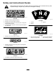
Safety and Instructional Decals Safety decals and instructions are easily visible to the operator and are located near any area of potential danger. Replace any decal that is damaged or missing. decal99-7345 99-7345 decal131-8463 1. Warning—read the Operator's Manual. 131-8463 2. Warning—do not touch the hot surface. 1. Forward 2. Neutral 3. Entanglement hazard, belt—stay away from moving parts; keep all guards in place. 3. Reverse 4.
decal145-2262 145-2262 EFI Models Only 1. Off 4. Starting the engine—1) Sit in the driver's seat; 2) Disengage the parking brake; 3) Turn the key switch to the start position; 4) Push down on the pedal. 2. On 5. Shutting off the engine—1) Release the pedal; 2) Engage the parking brake; 3) Turn the key switch to the off position; 4) Remove the key from the key switch. 3.
decal145-2261 145-2261 1. Warning—read the Operator’s Manual. 3. Falling hazard; severing hazard of limbs—do not carry passengers in the bed; do not carry extra passengers in between the seats; do not put your arms or legs outside of the machine while operating. 2. Warning—receive proper training before operating the machine. 4. Tipping hazard—drive slowly across or up slopes; take turns slowly; do not exceed speeds of 25 kph (16 mph); drive slowly when hauling cargo; drive slowly on uneven terrain.
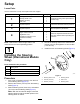
Setup Loose Parts Use the chart below to verify that all parts have been shipped. Procedure 1 2 3 4 Description Qty. Use Steering wheel Steering wheel cover Washer (1/2 inch) Dust cover 1 1 1 1 Install the steering wheel (International models only). No parts required – Check the fluid levels and tire pressure. No parts required – Burnish (break-in) the brakes.
2 4 Checking the Fluid Levels and Tire Pressure Reading the Manual and Viewing the Setup Material No Parts Required Parts needed for this procedure: Procedure 1. Check the engine-oil level before and after you first start the engine; refer to Checking the Engine-Oil Level (page 38). 2. Check the brake-fluid level before you first start the engine; refer to Checking the Brake-Fluid Level (page 51). 3.
Product Overview g033925 Figure 4 1. Hood latch 3. Steering wheel 5. Towing tongue 2. Shift lever 4. Cargo bed 6. Fuel cap 7. Cargo-bed lever g034517 Figure 5 1. Passenger handhold 3. Rear cargo-bed-accessory mount 2. Parking-brake lever 4.
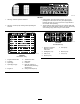
Controls Become familiar with all the controls before you start the engine and operate the machine. Control Panel g378787 Figure 6 1. Horn switch 6. Parking-brake lever 2. Light switch 7. USB power point 3. Gear-shift lever 8. Accelerator pedal 4. Hour meter 9. Brake pedal 5. Key switch CAUTION Accelerator Pedal Operating a machine with worn or incorrectly adjusted brakes can may result in personal injury. Use the accelerator pedal (Figure 6) to vary the ground speed of the machine.
Key Switch Gear-Shift Lever and Gear-Shift Indicator The key switch is located at the lower, right corner of the dash panel (Figure 6). The gear-shift lever can be set to 3 positions on the gear-shift indicator: FORWARD , REVERSE, and NEUTRAL (Figure 9). The key switch has 3 positions: OFF, ON, and START . There are 2 modes of starting the machine; refer to Starting the Engine (page 23). Note: The engine starts and runs in any of the 3 positions.
Horn Switch Fuel Gauge The horn switch is located on the control panel (Figure 6). Press the horn switch to sound the horn. The fuel gauge (Figure 10) is located on the fuel tank in the filler cap, at the left side of the machine. The gauge displays the amount of fuel in the tank. Light Switch Use the light switch (Figure 6) to illuminate the headlights. Push the light switch up to turn on the headlights. Push the light switch down to turn off the lights.
Specifications Note: Specifications and design are subject to change without notice. Base weight 397 kg (875 lb) Rated capacity (on level ground) 544 kg (1,200 lb) total, including 90.
Operation • Do not store the machine or fuel container where there is an open flame, spark, or pilot light, such as on a water heater or other appliance. Note: The procedures in this section show a machine with a plastic cargo bed and bucket seat; for additional procedures for other attachments, refer to the Operation section (if applicable) in the Installation Instructions. Visit www.Toro.com for your instructions or scan the QR code (if applicable) on your attachment.
Adding Fuel Recommended Fuel Type Unleaded gasoline Minimum octane rating 87 (US) or 91 (research octane; outside the US) Ethanol No more than 10% by volume Methanol None MTBE (methyl tertiary butyl ether) Less than 15% by volume Oil Do not add to the fuel Use only clean, fresh (no more than 30 days old), fuel from a reputable source. Important: To reduce starting problems, add fuel stabilizer/conditioner to fresh fuel as directed by the fuel-stabilizer/conditioner manufacturer.
• Before you start the machine, ensure that the • A break-in oil for the engine is not required. • • transmission is in neutral, the parking brake is engaged, and you are in the operating position. Original engine oil is the same type specified for regular oil changes. Refer to Maintenance (page 26) for any special, low-hour checks. Check the front suspension positioning and adjust it, if necessary; refer to Adjusting the Front Wheel Alignment (page 47).
• Do not operate the machine when there is the risk operating on a slope or if the load has a high center of gravity. Secure the load to the cargo bed of the machine to prevent the load from shifting. Take extra care when hauling loads that shift easily (e.g., liquids, rock, sand, etc.). of lightning. • Use accessories and attachments approved by The Toro® Company only. • Avoid starting, stopping, or turning the machine Multi-Passenger Safety on a slope, especially with a load.
Operating the Cargo Bed Raising the Cargo Bed to the Dump Position WARNING A raised bed could fall and injure persons that are working beneath it. • Always use the prop rod to hold the bed up before working under the bed. g034019 Figure 14 • Remove any load material from the bed before raising it. 1. Cargo-bed lever 2. WARNING Pull the prop rod into the dump position detent slot to secure the bed for dumping (Figure 15).
Opening the Tailgate Raising the Cargo Bed to the Service Position 1. Ensure that the cargo bed is down and latched. 1. Pull the lever on left, inside of the cargo bed toward you and lift the cargo bed up (Figure 14). 2. Using both hands, raise the tailgate using the ridge near the top of the tailgate (Figure 16). 2. Pull prop rod into the service position detent slot to secure the bed for maintenance (Figure 15). 3.
Closing the Tailgate Using the Rear Cargo Bed Accessory Mount If you unloaded loose material such as sand, landscaping rock, or wood chips from the cargo bed of the machine, some of the material that you unloaded may have lodged in the hinge area of the tailgate. Perform the following steps before closing the tailgate. 1. Use your hands to remove as much of the material from the hinge area as possible. 2. Rotate the tailgate to approximately the 45° position (Figure 17).
Loading the Cargo Bed Material Density Maximum Cargo Bed Capacity (on level ground) Gravel, dry 1522 kg/m3 (95 lb/ft3) Full limit the weight of the load that you carry in the cargo bed as described in Specifications (page 15) and on the gross vehicle weight tag of the machine.
After Operation Note: If the engine is cold, press and hold the accelerator pedal about half-way down, and pull the choke knob out to the ON position. Return the choke knob to the OFF position after the engine warms up. After Operation Safety General Safety Stopping the Machine • Before you leave the operating position, do the Important: When stopping the machine on following: an incline, use the service brakes to stop the machine and engage the parking brake to hold the machine in place.
Towing the Machine In case of an emergency, you can tow the machine for a short distance; however, this should not be a standard operating procedure. WARNING Towing at excessive speeds could cause a loss of steering control, resulting in personal injury. Never tow the machine at faster than 8 km/h (5 mph). g236535 Figure 20 1. Towing tongue and tie-down point (front of the machine) Towing the machine is a 2-person job.
Maintenance Note: The procedures in this section show a machine with a plastic cargo bed and bucket seat; for additional procedures for other attachments, refer to the Maintenance section (if applicable) in the Installation Instructions. Visit www.Toro.com for your instructions or scan the QR code (if applicable) on your attachment. Maintenance Safety • If major repairs are ever necessary or assistance is required, contact an authorized Toro distributor.
Recommended Maintenance Schedule(s) Maintenance Service Interval Maintenance Procedure After the first 5 hours • Change the engine oil. After the first 8 hours • Check the condition of the drive belt. • Check the tension of the starter-generator belt. After the first 50 hours • Check the air filter for the carbon canister. After the first 100 hours • Perform the guidelines for breaking in a new machine. Before each use or daily • Inspect the seat belt(s) for wear, cuts, and other damage.
WARNING Failure to properly maintain the machine could result in premature failure of machine systems, causing possible harm to you or bystanders. Keep the machine well maintained and in good working order as indicated in these instructions. CAUTION Only qualified and authorized personnel should maintain, repair, adjust, or inspect the machine. • Avoid fire hazards and have fire-protection equipment present in the work area.
Daily Maintenance Checklist Duplicate this page for routine use. Maintenance Check Item For the week of: Monday Tuesday Wednesday Thursday Friday Saturday Sunday Check the brake and parking brake operation. Check the gear shift/neutral operation. Check the fuel level. Check the engine-oil level. Check the brake-fluid level. Check the transaxle-fluid level. Inspect the air filter. Inspect the engine-cooling fins. Check for unusual engine noises. Check for unusual operating noises.
Pre-Maintenance Procedures Preparing the Machine for Maintenance 1. Park the machine on a level surface. 2. Shift the transmission to the NEUTRAL position. 3. Engage the parking brake. 4. Shut off the engine and remove the key. 5. Empty and raise the cargo bed. g034043 Figure 22 1. Front lifting point • The lifting point at the rear of the machine is Lifting the Machine located under the axle tubes (Figure 23). DANGER The machine may be unstable when using a jack.
Accessing the Hood Raising and Lowering the Seat Assembly Raising the Hood 1. To raise the seat assembly, push the seat assembly forward until it rests on the steering wheel (Figure 25). Lift up the handle of the rubber latches on each side of the hood (Figure 24). To lower the seat assembly, push the seat assembly rearward until it seats back into the original position (Figure 25). g034045 Figure 24 2. Raise the hood. g190066 Figure 25 Closing the Hood 1. Gently lower the hood. 2.
g190187 Figure 26 1. Pins Installing a Bucket Seat Slide the seat assembly onto the pins and lower the seat assembly (Figure 27). g237191 Figure 28 Installing a Bench Cushion Slide the bench cushion onto the pins and lower the cushion (Figure 29). g190186 Figure 27 1. Pins Removing a Bench Cushion 1. Push the bench cushion forward to the raised position. 2. Slide the cushion to the side, out of the pins, and lift the cushion upward (Figure 28).
Lubrication Greasing the Front Wheel Bearings Service Interval: Every 300 hours Grease specification: Mobilgrease XHP™-222 Removing the Hub and Rotor 1. 2. Lift the front of the machine and support it with jack stands. g033047 Figure 31 Remove the 4 lug nuts that secure the wheel to the hub (Figure 30). 1. Flange-head bolts (3/8 x 3/4 inch) 3. Caliper bracket (brake assembly) 2. Spindle 4. Remove the dust cap from the hub (Figure 32). g033046 Figure 30 g192346 1. Hub 3. Lug nut Figure 32 2.
Greasing the Wheel Bearings 1. Remove the outboard bearing and bearing race from the hub (Figure 34). g192347 Figure 33 1. Spindle 2. Hub and rotor assembly 7. Wipe clean the spindle with a rag. 8. Repeat steps 1 through 7 to the hub and rotor at the other side of the machine. g033050 Figure 34 1. Seal 4. Bearing cavity (hub) 2. Inboard bearing 5. Outboard-bearing race 3. Inboard-bearing race 6. Outboard bearing 2. Remove the seal, inboard bearing from the hub (Figure 34). 3.
Installing the Hub and Rotor 1. Apply a light coat of the specified grease to the spindle (Figure 35). g192345 Figure 36 g192344 1. Cotter pin Figure 35 1. Nut retainer 4. Outer bearing 2. Spindle nut 5. Hub, rotor, inner bearing, race, and seal 6. Spindle 3. Tab washer 3. Dust cap 2. Nut retainer 9. Install the cotter pin and bend each legs around the retainer (Figure 36). 10. Install the dust cap onto the hub (Figure 36).
Engine Maintenance Engine Safety • Shut off the engine, remove the key, and wait for all moving parts to stop before checking the oil or adding oil to the crankcase. • Keep your hands, feet, face, clothing, and other body parts away from the muffler and other hot surfaces. Servicing the Air Cleaner Servicing the Air-Cleaner Cover Service Interval: Every 50 hours—Remove the air-cleaner cover and clean out the debris. Do not remove the air-cleaner element.
Replacing the Air-Cleaner Element Service Interval: Every 50 hours—Under special operating conditions (refer to Maintaining the Machine under Special Operating Conditions)—replace the air-cleaner element. Replace the air-cleaner element sooner if dirty or damaged. Every 100 hours—Under normal operating conditions—replace the air-cleaner element. Replace the air-cleaner element sooner if dirty or damaged.
Servicing the Engine Oil Engine-Oil Specifications Crankcase Capacity: 1.0 L (1.1 US qt) Oil Type: API service class SJ or higher detergent oil Viscosity: See the table below. g192771 g034082 Figure 40 Figure 39 Checking the Engine-Oil Level Service Interval: Before each use or daily Note: The machine is shipped with oil in the crankcase; however, check the oil before and after you start the engine.
Changing the Engine Oil Servicing the Spark Plug Service Interval: After the first 5 hours—Change the engine oil. Checking and Replacing the Spark Plug Every 50 hours—Under special operating conditions (refer to Maintaining the Machine under Special Operating Conditions)—change the engine oil. Service Interval: Every 100 hours/Yearly (whichever comes first) Replace the spark plug if necessary. Every 100 hours—Under normal operating conditions—change the engine oil.
8. Fuel System Maintenance Repeat steps 1 through 7 for the other spark plug. Adjusting the High/Low Idle 1. Lift the cargo bed and secure it with the prop rod. 2. At the throttle cable housing, loosen the forward jam nut and tighten the rear jam nut to increase the low idle (Figure 43). Inspecting Fuel Lines and Connections Service Interval: Every 400 hours/Yearly (whichever comes first) Inspect the fuel lines, fittings, and clamps for signs of leaking, deterioration, damage, or loose connections.
Servicing the Carbon Canister Checking the Air Filter for the Carbon Canister Service Interval: After the first 50 hours Every 200 hours Check the opening at the bottom of the air filter for the carbon canister to ensure that it is clean and free of debris and obstructions (Figure 45). Clean the air filter for the carbon canister with clean, compressed air. g029685 g034099 Figure 44 7.
Disconnecting the Battery Electrical System Maintenance WARNING Incorrect battery cable routing could damage the machine and cables, causing sparks. Sparks can cause the battery gasses to explode, resulting in personal injury. Electrical System Safety • Disconnect the battery before repairing the machine. Disconnect the negative terminal first and the positive last. Connect the positive terminal first and the negative last.
Removing the Battery 1. Disconnect the battery cables; refer to Disconnecting the Battery (page 42). 2. Remove the battery as shown in Figure 47. Installing the Battery 1. Install the battery as shown in Figure 48. g034327 Figure 48 g034326 2. Figure 47 43 Connect the battery cables; refer to Connecting the Battery (page 44).
Connecting the Battery Replacing the Fuses Connect the battery as shown in Figure 49. There are 5 fuses in the electrical system; the other slots are open for options. They are located beneath the seat assembly (Figure 50). Horn 20 A Main power 15 A Headlights 10 A USB power point/options 10 A Fuel 10 A Optional lift kit—open 15 A g034315 Figure 49 Charging the Battery WARNING Charging the battery produces gasses that can explode.
Maintaining the Headlights 7. Secure the headlight assembly with the speed clips that you removed in step 4. Replacing the Headlight 8. Connect the electrical connector for the harness to the connector of the lamp assembly (Figure 51). 9. Adjust the headlights to direct the beams to the desired position, refer to Adjusting the Headlights (page 45). Specification: See your Parts Catalog. 1. Disconnect the battery; refer to Disconnecting the Battery (page 42). 2. Open the hood. 3.
Drive System Maintenance Inspecting the Steering and Suspension Components Maintaining the Tires Service Interval: Every 100 hours—Inspect the steering and suspension for loose or damaged components. Service Interval: Every 100 hours—Check the condition of the tires and rims. Inspect the tires and rims for signs of wear and damage. With the steering wheel at the centered position (Figure 53), turn the steering wheel to the left or right.
Adjusting the Front Wheel Alignment Adjusting the Front Wheel Toe-in Important: Before adjusting toe-in, ensure that the camber adjustment is as close to neutral as possible; refer to Adjusting the Camber (page 47). Service Interval: Every 100 hours/Yearly (whichever comes first)—Check the front wheel camber and toe-in. 1. Preparing to Adjust Camber or Toe-in 1. Check the tire pressure to ensure that the front tires are inflated to 82 kPa (12 psi). 2.
Checking the Transaxle-Fluid Level 3. Remove the drain plug and the seal, and allow the fluid to drain completely (Figure 58). Note: Retain the drain plug and seal for installation in step 4. Service Interval: Every 100 hours Fluid Type: SAE 80W-90 (API MT-1) or SAE 80W-90 (API GL-5) 1. Park the machine on a level surface. 2. Engage the parking brake. 3. Shut off the engine and remove the key. 4. Remove the fill plug on the transaxle (Figure 58). 4.
Adjusting the Neutral Gear-Shift Position 1. Loosen the jam nuts on the gear-shift cable and adjust them as necessary (Figure 59). g011947 Figure 60 1. Cover g034455 3. Thoroughly clean the inside of the cover and the inner components of the clutch using compressed air. 4. Install the clutch cover and secure it with the 3 bolts (Figure 60) that you removed in 2. 5. Lower the cargo bed. Figure 59 1. Shift lever 2. Spanner bar 2. 3. 3. Gear-shift cable 4.
Cooling System Maintenance Cooling System Safety • Swallowing engine coolant can cause poisoning; keep out of reach from children and pets. • Discharge of hot, pressurized coolant or touching a hot radiator and surrounding parts can cause severe burns. g026341 – Always allow the engine to cool at least 15 minutes before removing the radiator cap. Figure 61 1. Clutch spacer – Use a rag when opening the radiator cap, and open the cap slowly to allow steam to escape. 3. Remove the spring. 4.
Brake Maintenance 8. Checking the Parking Brake 1. Engage the parking brake by pulling the parking-brake lever toward you, until you feel tension. 2. If you do not feel tension when pulling the parking-brake toward you within 11.4 to 16.5 cm (4-1/2 to 6-1/2 inches) from the “P” symbol on the dash, then you need to adjust the parking brake; refer to Adjusting the Parking Brake (page 51). Verify that the parking brake is adjusted to the proper tension; refer to Checking the Parking Brake (page 51).
Replacing the Service and Parking-Brake Pads Service Interval: Every 400 hours Contact your authorized Toro distributor to inspect and possibly replace the service and parking-brake pads. Changing the Brake Fluid g002136 Service Interval: Every 1,000 hours Figure 64 1. Brake-fluid reservoir 6. Contact your authorized Toro distributor. 2. Minimum line If the fluid level is low, perform the following: A. Clean the area around the reservoir cap and remove the cap (Figure 63). B.
Belt Maintenance Replacing the Drive Belt Servicing the Drive Belt 1. Raise the cargo bed; refer to Raising the Cargo Bed to the Dump Position (page 20). 2. Shift the transmission into the NEUTRAL position, engage the parking brake, rotate the key switch to the OFF position, and remove the key. 3. Rotate and route the belt over the secondary clutch (Figure 65). 4. Checking the Drive Belt Service Interval: After the first 8 hours Every 200 hours 1. Park the machine on a level surface.
Chassis Maintenance Cleaning Adjusting the Cargo-Bed Latches Washing the Machine Service Interval: Before each use or daily—Wash the machine. If the cargo-bed latch is out of adjustment, the cargo bed vibrates up and down as you drive the machine. You can adjust the latch posts to make the latches hold the cargo bed snugly to the chassis. 1. Wash the machine as needed using water alone or with a mild detergent. You may use a rag when washing the machine.
Storage D. Start the engine again and run it until it stops. Storage Safety E. Choke the engine. F. Start and run the engine until it does not start again. • Shut off the machine, remove the key, and wait for all movement to stop before you leave the operator’s position. Allow the machine to cool before adjusting, servicing, cleaning, or storing it. • Do not store the machine or fuel container where there is an open flame, spark, or pilot light, such as on a water heater or other appliance.
Notes:
California Proposition 65 Warning Information What is this warning? You may see a product for sale that has a warning label like the following: WARNING: Cancer and Reproductive Harm—www.p65Warnings.ca.gov. What is Prop 65? Prop 65 applies to any company operating in California, selling products in California, or manufacturing products that may be sold in or brought into California.
EEA/UK Privacy Notice Toro’s Use of Your Personal Information The Toro Company (“Toro”) respects your privacy. When you purchase our products, we may collect certain personal information about you, either directly from you or through your local Toro company or dealer.
The Toro Warranty Two-Year or 1,500 Hours Limited Warranty Parts Conditions and Products Covered The Toro Company warrants your Toro Commercial product (“Product”) to be free from defects in materials or workmanship for 2 years or 1,500 operational hours*, whichever occurs first. This warranty is applicable to all products with the exception of Aerators (refer to separate warranty statements for these products).