
Installation Instructions

7
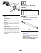
SettingtheParking-Brake
Tension
NoPartsRequired
Procedure
1.Ensurethattheparkingbrakeisdisengaged.
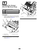
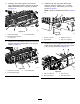
2.Using2wrenches,holdtheadjustingpostonthe
caliperinplacewith1wrench,andloosenthe
jamnut1/4turnwiththeotherwrench(Figure
15).
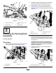
g034434
Figure15
1.Adjustingpost
3.Caliper
2.Jamnut
3.Whileholdingtheadjustingpostandthejam
nutinplace,turntheadjustingpostintotighten
(Figure15).
Note:Performthisstepuntilyoufeeldragon
thewheel.
4.Whileholdingtheadjustingpostandthejamnut
inplace,backoff1/4turn(Figure15).
5.Whileholdingtheadjustingpostandthejamnut
inplace,tightenthejamnut(Figure15).
6.Repeatthisproceduretotheotherside.
7.Verifythattheparkingbrakeisadjustedto
thepropertensionbyperformingthefollowing
procedure:
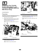
A.Engagetheparkingbrakebypullingthe
parking-brakelevertowardyou,untilyou
feeltension.
B.Ifyoudonotfeeltensionwhenpullingthe
parking-braketowardyouwithin11.4to
16.5cm(4-1/2to6-1/2inches)fromthe
“P”symbolonthedash,thenyouneedto
adjusttheparkingbrake.
8
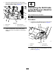
InstallingtheFloor-Plate
SupportBrackets
Partsneededforthisprocedure:
2Floor-platesupportbracket
8
Thread-formingscrew(5/16x3/4inch)
Procedure
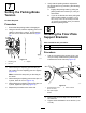
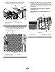
1.Usethe4thread-formingscrews(5/16x3/4
inch)tolooselyinstalltheoor-platesupport
brackettotheframechannel(Figure16).
g191566
Figure16
1.Thread-formingscrew
(5/16x3/4inch)
3.Framechannel
2.Floor-platesupport
bracket
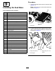
2.Performtheprevioussteptotheothersideof
themachine.
3.Tightenallthehardwareto23to26N∙m(17to
19ft-lb).
7