
Installation Instructions


22
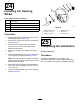
InstallingtheHitch
Assembly
Partsneededforthisprocedure:
1Hitchassembly
1
Flange-headbolt(1/2x2-1/4inches)
1
Locknut(1/2inch)
Procedure
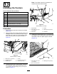
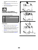
Installthehitchassemblytothereceivertubeusing
theange-headbolt(1/2x2-1/4inches)andlocknut
(1/2inch)asshowninFigure63.
g198862
Figure63
1.Flange-headbolt(1/2x
2-1/4inches)
3.Hitchassembly
2.Receivertube
4.Locknut(1/2inch)
23
InstallingtheCargoBed
LatchStrikers
NoPartsRequired
Procedure
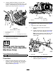
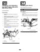
1.Removethetopange-headbolt(3/8x2-1/2
inches)andangenut(3/8inch)fromtherear
frametube(Figure64).
2.Loosentheangenut(3/8inch)securingthe
cargobedlatchstriker,androtatethecargobed
latchstriker90°asshowninFigure64.
3.Securethetopofthecargobedlatchstriker
totherearframetubeusingthepreviously
removedange-headbolt(3/8x2-1/2inches)
andangenut(3/8inch)asshowninFigure64.
4.Securethebottomofthecargobedlatchstriker
bytighteningtheangenut(3/8inch).
5.Repeatthisprocedurefortheothercargobed
latchstriker.
g199056
Figure64
1.Flangenut(3/8inch)3.Cargobedlatchstriker
2.Flange-headbolt(3/8x
2-1/2inches)
28