
Maintenance Guide

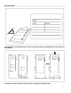
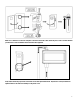
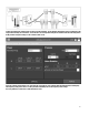
Table Of Contents
- Introduction
- FTElectric Manual v2.2.0.0 (CDL)
- Types of Electric Fire Pump Controllers
- Methods of Starting/Stopping
- FCC Regulations and Radio Standards Specification (RSS) Rules
- Location
- Mounting
- Storage
- Wiring and Connections
- Water Connections
- Electrical Wiring
- Electrical Connections
- Energy Consumption
- Sizing
- Incoming Power Connections
- Motor Connections
- Terminal Strip Descriptions
- Quick Start-Up Guide
- The Mark III
- Alarm Bell
- First Setup
- Mark III: Manual Rebooting Method
- Pressure Transducer Test
- Home (Menu)
- Screen Saver
- Alarms (Menu)
- Config (Menu)
- History (Menu)
- Service
- Installation
- Main Features
- Home
- Alarms
- Configuration
- History
- Service
- Download Manuals
- Language
- Technical Documents

9
Verify that the normal voltage shown at L1-L2, L2-L3 and L1-L3 (nominal) is the same as what is written on the fire pump
controllers nameplate. The fire pump controller will validate the nominal voltage automatically versus what it has been built
for.
If all is adequate green check marks will appear.