
Maintenance Guide

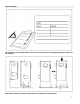
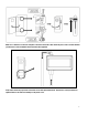
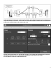
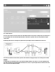
Table Of Contents
- Introduction
- FTElectric Manual v2.2.0.0 (CDL)
- Types of Electric Fire Pump Controllers
- Methods of Starting/Stopping
- FCC Regulations and Radio Standards Specification (RSS) Rules
- Location
- Mounting
- Storage
- Wiring and Connections
- Water Connections
- Electrical Wiring
- Electrical Connections
- Energy Consumption
- Sizing
- Incoming Power Connections
- Motor Connections
- Terminal Strip Descriptions
- Quick Start-Up Guide
- The Mark III
- Alarm Bell
- First Setup
- Mark III: Manual Rebooting Method
- Pressure Transducer Test
- Home (Menu)
- Screen Saver
- Alarms (Menu)
- Config (Menu)
- History (Menu)
- Service
- Installation
- Main Features
- Home
- Alarms
- Configuration
- History
- Service
- Download Manuals
- Language
- Technical Documents

5
Electrical Connections
A licensed electrician must supervise the electrical connections. The dimension drawings show the area suitable for
incoming power and motor connections. No other location shall be used. Only watertight hub fittings shall be used when
entering the cabinet to preserve the NEMA rating of the cabinet.
The installer is responsible for adequate protection of the fire pump controller components against metallic debris or drilling
chips. Failure to do so may cause injuries to personnel, damage the controller and subsequently void warranty.
Energy Consumption
Standby power: 10W
Sizing
Incoming power terminals on the controller are suitable to accept wire based on that selection with insulation not less than
60°C. (Refer to terminal diagram for terminal sizes.)
The electrical wiring between the fire pump controller and the pump motor shall be in rigid, intermediate, or liquid tight
flexible metal conduit or Type MI cable and meet the requirements of NFPA 70 National Electrical Code or other local codes.
The number of conductors required varies depending on the model of starter:
3-wires plus ground sized at 125% of full load current for models FTA1000, FTA1800, FTA1930 and FTA1500.
6-wires plus ground sized at 125% of 50% of the motor full load current for FTA1250 model.
6-wires plus ground sized at 125% of 58% of the motor full load current for FTA1300 and FTA1350 models.
Incoming Power Connections
Incoming normal power is to be connected to terminals located on the disconnecting means IS.
- For 3 phases motor: identified L1-L2 and L3.
- For single phase motor: identified L1 and L3
Motor Connections
Motor wires shall be connected to terminals identified by:
- T1-T2 and T3 located on main contactor (1M) for models FTA1000, FTA1800, FTA1930 and FTA1500
- T1-T2 and T3 located on contactor (1M) and T7-T8 and T9 located on contactor (2M) for model FTA1250
- T1-T2 and T3 located on contactor (1M) and T6-T4 and T5 located on contactor (2M) for models FTA1300 and FTA1350
It is the responsibility of the installer to obtain connection information on the motor and to assure that the motor is
connected as per the motor manufacturer recommendations. Failure to do so may cause injuries to personnel, damage the
motor and/or the controller and subsequently void warranty on both items.
Terminal Strip Descriptions
Electric IO Board
For full terminal strip description consult full manual.