
User's Manual


Shenzhen TOPFLYtech Co., Limited. All Rights Reserved 5
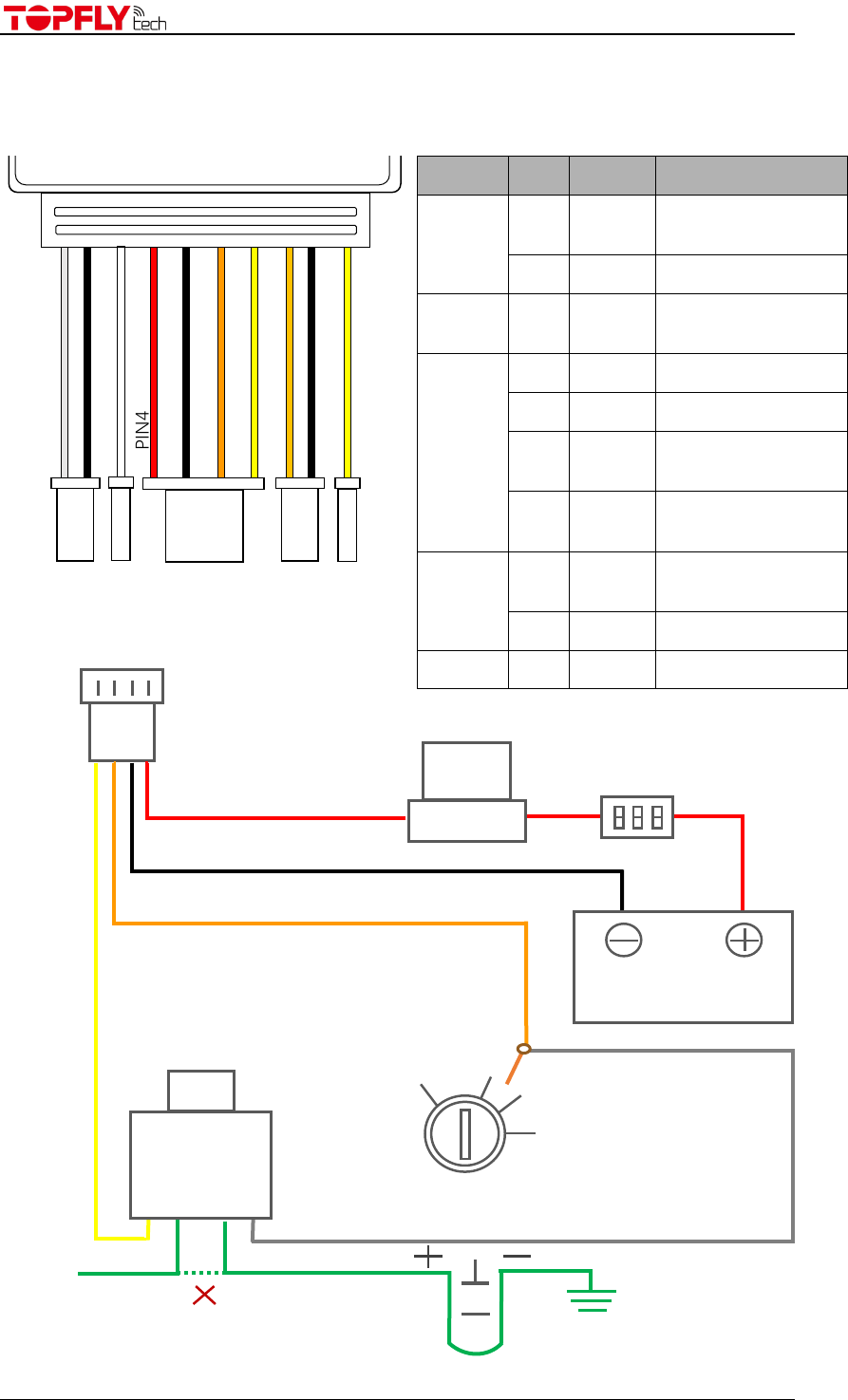
1. Quick Reference of Connection Diagram
Cut off
Engine Starter
White
Yellow
ACC
ON
START
OFF
Key
Position
Relay
12V or 24V
Orange
Black
Red
Vehicle Battery
12V or 24V
2A Fuse
Fuse Box
Fuse
PIN4
PIN6
PIN7
PIN5
Connector1
Connector5
Connector2
Connector
PIN
Color
Function
1
1
Gray
Configurable Input2
(Digital/Analog)
2
Black
GND
2
3
White
Configurable Input1
(Digital/Analog)
3
4
Red
Power+
5
Black
Power-
6
Orange
Ignition Detection
(Digital input1)
7
Yellow
Relay Control
(Digital output1)
4
8
Orange
SOS Button
(Digital input2)
9
Black
GND
5
10
Yellow
Digital output2
PIN1
PIN2
PIN8
PIN9
PIN3
PIN10
Connector3
Connector4