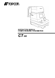
INSTRUCTION MANUAL COMPUTERIZED TONOMETER CT-80
INTRODUCTION Thank you for purchasing the TOPCON Computerized Tonometer CT-80. (To get the best use from the instrument, please carefully read these instructions and keep this Instruction Manual in a convenient location for future reference.) This instrument features the following: • An exact, non-contact intraocular pressure measurement that can be done by air ejection. • An alignment bar that enables easy operation.
DISPLAY FOR SAFE USE In order to encourage the safe use of the product and prevent any danger to the operator and others or damage to properties, important warnings are placed on the product and inserted in the instruction manual. We suggest that everyone understand the meaning of the following displays and icons before reading the “Safety Cautions” and text. DISPLAY MEANING WARNING Ignoring or disregarding this display may lead to death or serious injury.
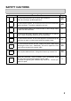
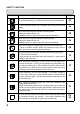
SAFETY CAUTIONS WARNING Icons Prevention item Page To avoid electrical shock, do not open the instrument. Refer all servicing to qualified personnel. 45 To avoid electric shocks, do not remove the covers from the bottom and top surfaces, TV monitor, measuring unit, etc. 45 To prevent shock hazard, do not allow water or other foreign matter to enter into the instrument. — To avoid fire and electric shocks in case of tumbling, do not place a cup or vessel containing water/fluid on the instrument.
SAFETY CAUTIONS CAUTION Icon 4 Prevention item Page To avoid potential injury, hold the instrument in the proper position. 13 To avoid electrical shock, do not handle the power plug with wet fingers. 14 Never insert your fingers under the measuring head. ∗ Inform the patient of this, too. Careless insertion of fingers may cause injury by pinching. 30 Never insert your fingers under the measuring head. ∗ Inform the patient of this, too. Careless insertion of fingers may cause injury by pinching.
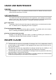
USAGE AND MAINTENANCE PURPOSE This tonometer “CT-80” is a precision electrical device for medical use that must be used under the instruction of a doctor. USER MAINTENANCE To maintain the safety and performance of the equipment, never attempt to do maintenance on your own. Ask our serviceman for repair except for the items specified here which can be maintained by the user. For details, follow the instructions.
WARNING INDICATIONS AND POSITIONS To ensure the safe usage of this equipment, precaution indications are provided. Abide by the following warning instructions. If any of the following labels are missing, please contact us at the address printed on the back cover of this manual. WARNING • To avoid electrical shock, do not open the instrument. Refer all servicing to qualified personnel. CAUTION • To avoid potential injury during operation, do not touch the patient’s eyes or nose with the instrument.
CONTENT Introduction 1 INDIVIDUAL OPERATIONS Display for Safe Use 2 How to Print Out Measurement Values 42 Safety Cautions 3 How to Correct Measurement Values 43 Usage and Maintenance 5 Input/Output via RS-232C 44 Escape Clause 5 Warning Indications and Positions 6 BEFORE REQUESTING SERVICE Checking Operations NAMES OF COMPONENTS Main Body Components 8 Control Panel Components 9 45 REFERENCE Optional Accessories 46 Monitor Screen Components 10 Specifications & Performance 46 C
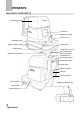
COMPONENTS MAIN BODY COMPONENTS Measuring head TV Monitor Measuring switch Control lever Clamping knob Safety stopper knob Control panel External I/O terminal Power lamp Fixing knob (used to stop movements during removal) Forehead rest Measuring window Measuring nozzle Height mark Chinrest pad pin Chinrest Chinrest handle Power switch Power cable Adjusting knob 8 COMPONENTS Measuring window cap
CONTROL PANEL COMPONENTS Clear switch Print switch Down switch Menu switch Air check switch Auto/Manual switch Select switch Range switch Up switch Print switch ................... Prints out the screen readings. When there is no reading, holding the switch down feeds the paper. Range switch ................ Switches the range between 0-30 and 0-60. Clear switch .................. Deletes all the measurement values from the screen. Menu switch .................. Displays the Menu screen.
MONITOR SCREEN COMPONENTS Measurement Screen (Auto mode, alignment) Target eye Measurement mode Measuring range Alignment dot Outer alignment mark Alignment bar Inner alignment mark Measurement Screen (Manual mode, alignment OK) Outer alignment mark Inner alignment mark (alignment OK) Menu Screen Cursor 10 COMPONENTS
CONTENTS OF PRINTER OUTPUT Bar code Equipment No. Work ID No. ID No.
STANDARD ACCESSORIES The following are the standard accessories. The figures in parentheses are the quantities. Please check to see that all accessories are contained.
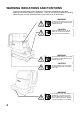
PREPARATIONS HOW TO INSTALL THE INSTRUMENT 1 2 CAUTION Before carrying the instrument, be sure to affix it firmly by turning the fixing screw at the base. If the instrument is moved with the screw loosened, it may result in damage to the instrument. CAUTION When moving the instrument, be sure to hold it at the bottom surface with two people. Carrying by one person may cause back injury or injury by falling parts.
HOW TO CONNECT THE POWER CABLE CAUTION 1 2 3 Make sure the To avoid electrical shock, do not handle the power plug with wet fingers. POWER SWITCH is OFF. Attach the power cable to the machine body. Plug the power cable into the 3-pin AC receptacle with grounding. HOW TO CONNECT EXTERNAL I/O TERMINALS RS-232C OUT This machine can be connected to another device, including a personal computer via the RS-232C OUT terminal. 1 2 Connect the cable to the RS-232C OUT terminal of this machine.
INITIAL SETTINGS During the initial setting, date, time, operating time of the power save function, RS232C, mode of average value, buzzer and message can be set. Preparations 1 2 Make sure the power cable is connected. For connection, see “HOW TO CONNECT THE POWER CABLE” on page 14. Check the no-patient condition of the instrument and turn the • MEMO POWER SWITCH ON.
Time/Date Setting Example of operation: Illustrations show time setting. 1 2 Press Press press on the control panel to get the Menu screen. , on the control panel, move the cursor to “DATE/TIME SET” and MEASUREMENT SWITCH . The Date/Time setting screen is displayed. 3 Make sure that the display “BATTERY → O.K.” appears. If the display is “BATTERY → N.G.”, the built-in clock battery is used up. Contact your dealer.
5 6 Press of the control panel, renew figures and press , The renewed figures are inputted. Press , MEASUREMENT SWITCH . of the control panel, move the cursor to “EXIT” and press MEASUREMENT SWITCH . Date and other items can also be renewed at the same time. Setting The Power Save Time A time for the power save function to achvale can be selected from 10, 20, 30 or 60min. For shipment, 10min. is set. 1 2 Return to the Menu screen.
5 ↔ 10 ↔ 20 ↔ 30 ↔ 60 4 Press MEASUREMENT SWITCH . The Menu screen is displayed. RS-232C INPUT/OUTPUT Settings For shipment, settings are EQUIPMENT (Equipment No.) No.1, FORMAT (communication mode) OFF, and SPEED (communication speed) 2400 Each time Example: is pressed, theequipment display changes , Setting the No. as follows: 1 2 Return to the Menu screen. Press , of the control panel, move the cursor to “RS-232C MODE” and press MEASUREMENT SWITCH . The RS-232C Mode is displayed.
3 Press , on the control panel, move the cursor to “EQUIPMENT” and press MEASUREMENT SWITCH 4 Press , . on the control panel, change the equipment No. and press MEASUREMENT SWITCH . The equipment No.(EQUIPMENT) can be selected from 0000 to 0099. Each time is pressed, the display changes as follows: , OFF ↔ MODE1 ↔ MODE2 ↔ MODE3 ↔ MODE4 ↔ When setting the speed, the display changes from 2400-9600 each time pressed. is , 2400 ↔ 9600 “EQUIPMENT” and “WORK ID NO.
Setting The Average Value Mode The average value display of the measurement values can be selected from integer and decimal displays. For shipment, the integer display is set. 1 2 Return to the Menu screen. Press press , on the control panel, move the cursor to “AVERAGE MODE” and MEASUREMENT SWITCH . The Average Value Mode screen is displayed. 3 Press 20 PREPARATIONS , on the control panel to change the mode.
15 : The average value is displayed as an integer (by rounding fractions to the nearest whole number). 15.0 : The average value is displayed up to one decimal (by rounding fractions to the nearest tenth). 4 Press MEASUREMENT SWITCH . The Menu screen returns. Setting The Buzzer The buzzer can be turned ON/OFF by pressing the switches on the control panel. 1 2 Return to the Menu screen. Press , on the control panel, move the cursor to “BUZZER SET” and press MEASUREMENT SWITCH .
4 Press MEASUREMENT SWITCH . The Menu screen returns. Message Input You can add a brief message to the printout. 1 2 Return to the Menu screen. Press press , on the control panel, move the cursor to “MESSAGE INPUT” and MEASUREMENT SWITCH . The Message Input screen is displayed. Input column Selection column 3 Press on the control panel to move the blinking icon to a character , , , in the selection column for input.
■ : A space for 1 character (Use this to delete a character, too.) STEP : The blinking icon of the input column moves right. BACK : The blinking icon of the input column moves left. 4 5 Press MEASUREMENT SWITCH . The character selected by the blinking icon is inputted. Press , , , on the control panel, move the blinking icon in the selection column to “EXIT” and press MEASUREMENT SWITCH . The Menu screen is displayed.
2 Slide the paper roll onto the paper shaft, paying attention to the direction of unwinding, and pull out the top of the paper 7-8cm. Unwinding direction 3 Insert the paper straight into the printer along the paper guide. 4 5 6 When the top of the paper stops inside the printer, press to further insert the paper into the printer. Paper feeding starts when the top of the paper reaches a certain depth inside the printer.
7 Return the paper retainer lever back to its original position. 8 Reset the printer cover, holding the top of the paper outside. The paper is not fed unless the paper retainer lever is lowered. Use the following 58mm wide printer paper: TF50KS-E2C Using another paper may cause a printing noise or thin prints.
Manual Setting 1 2 Press the printer cover with your thumb, slide it aside and remove. Slide the paper roll onto the paper shaft, paying attention to the direction of unwinding, and pull out the top of the paper 7∼8cm. 3 Turn the paper retainer lever in the arrow direction. 4 Cut the paper on the control lever Paper side atretainer about 2cm.
5 Insert the paper straight into the printer along the paper guide. 6 Further insert the paper and draw out the top of the paper from the outlet. 7 Adjust the paper so that it comes out straight from the outlet, and then lower the paper retainer lever. The paper does not easily pass through the printer unless it is cut on the control lever side.
8 Set the printer cover, holding the top of the paper outside. If the paper is jammed, turn the paper retainer lever to the illustrated position, and take out the jammed paper from the printer. HOW TO RESET FROM POWER SAVE STATUS This machine employs a power save function. If the machine is not used during a set time, the power save function stops supplying power to the monitor and CCD camera. Under the power save status, the POWER lamp of the control panel flashes. 1 Press MEASUREMENT SWITCH .
BASIC OPERATIONS PREPARATIONS BEFORE MEASUREMENT Turn ON the Power 1 2 3 Make sure the power cable is connected. For connection, see “HOW TO CONNECT THE POWER CABLE” on page 14. Make sure the instrument is in the no-patient condition and turn ON the POWER SWITCH . The Title screen is displayed, and then the Measurement screen is displayed. Air Check This machine is equipped with a function for checking the correct operations measurement system inside the instrument.
If “NG (+)” or “NG (-)” is displayed, an anomaly has occurred. Turn OFF the POWER SWITCH , and check whether or not there is any obstacle in front of the measuring nozzle. If there is an object, remove it, and then press the POWER SWITCH . Press and perform the checking procedure again. If no object is there, a problem has occurred. Turn OFF the POWER SWITCH , unplug the power cable, and call your dealer. Setting the Patient CAUTION 1 2 3 4 Never insert your fingers under the measuring head.
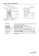
5 Adjust the height of the chinrest, by operating the chinrest handle, so that the tail of the patient's eye becomes level with the height mark of the chinrest post. Height mark Chinrest handle Setting the Safety Stopper 1 2 3 CAUTION Before measuring, set the safety stopper. If the safety stopper is not set, it may cause injury to the eye that comes in contact with the measuring window glass. Set the safety stopper separately for the right and left eyes.
4 When the measuring nozzle reaches a position 8∼10mm from the cornea, release the safety stopper knob. 8∼10mm 5 Holding the control lever, try to slightly push out the machine body to make sure the stopper is working. If the machine body does not move forward any further, the setting is completed.
MEASUREMENT UNDER AUTO MODE MEMO • Adjust the height of the automatic instrument table so that correct measurement values can be obtained by allowing the patient to undergo measurements in a comfortable position. • Make the patient relaxed so as to secure correct measurement values; make sure the patient does not hold his breath or remain tense. Setting the Measurement Mode The initial status of the measurement mode is AUTO, upon turning the power ON. 1 2 Return to the Measurement screen.
Alignment and Measurement MEMO It is recommended that you do intraocular pressure measurements several times. Since the intraocular pressure varies by heart beats and tears, often it is not possible to obtain exact measurement values by measuring only once or twice. The alignment operation can be performed with the control lever. Moving the machine body by the control lever • When the machine body needs to be moved slightly back and forth or right and left, move the control lever in each direction.
1 2 3 4 Hold the control lever and pull the machine body towards the operator. Move the control lever in directions as needed and bring the patient’s eye to the center of the monitor screen. Tell the patient to gaze at the yellow-green light. Move the machine body toward the patient and focus the target eye. alignment dot becomes seen reflected in the cornea.
5 6 Move the machine body in directions as needed in order to get the alignment dot within the inner alignment mark on the monitor screen. Holding the alignment dot within the inner alignment mark, slightly push the machine body toward the patient. When the machine body approaches the target eye, the alignment bar and “FORWARD” display appear on the monitor screen.
Reference position 7 After the alignment bar is displayed, push the machine body out a little bit more. When the alignment is adjusted, measurement is done automatically and the measurement value is displayed on the monitor screen. Too far When the outer alignment mark is not displayed, measurement is not possible. After measurement Measurement can be done when the outer alignment mark is displayed after a few seconds MEMO • If measurement is not possible under the Auto mode, use the Manual mode.
Display of Measurement Values Measurement values are displayed on the monitor screen for up to three measurements. From the fourth measurement on, values of earlier measurements are deleted in order.
1 2 3 4 5 Hold the control lever and pull the machine body towards the operator. Move the control lever in directions as needed in order to bring the patient’s eye to the center of the monitor screen. Tell the patient to gaze at the yellow-green light. Move the machine body toward the patient and focus the target eye. A vague alignment dot becomes seen reflected in the cornea.
6 Holding the alignment dot within the inner alignment mark, slightly push the machine body toward the patient. When the machine body approaches the target eye, the alignment bar and the “FORWARD” display appear on the monitor screen. Alignment bar At this moment, be careful not to catch eyelashes and eyelids within the outer alignment mark so as to ensure correct measurements. See descriptions about the alignment bar, “FORWARD” and “TOO CLOSE” on page 36.
DELETING MEASUREMENT VALUES 1 Press on the control panel. All the measurement values of the right and left eyes are deleted and the instrument settings return to their status upon turning the power ON.
INDIVIDUAL OPERATIONS HOW TO PRINT OUT MEASUREMENT VALUES MEMO • To avoid printer problems due to paper jams, do not feed paper if it is torn or creased. • To avoid discoloring, particularly of the recording part, do not store the printer paper in holders made of materials containing plasticizers (ex., vinyl chloride). • To avoid coloring in the white part and discoloring in the recording part, do not use bonds containing solvents. Use water bonds.
3 Hold the paper and pull it diagonally to cut. MEMO • To avoid paper jams, cut the paper carefully and evenly. HOW TO CORRECT MEASUREMENT VALUES MEMO Never set the select switch for more than eight points to avoid malfunctions. Though the machine is adjusted for displaying optimal measurement values, the values can be corrected within a -4 ∼ +3mmHg range. 1 2 3 Make sure the power is OFF. Open the control panel lid. Using a screwdriver, turn the “ ” of the select switch.
INPUT/OUTPUT VIA RS-232C Output via RS-232C This machine can output data via the RS-232C interface to a personal computer or similar device. 1 2 3 4 Make sure the RS-232C OUT is connected. For connection, see “HOW TO CONNECT EXTERNAL I/O TERMINALS” on page 14. Check the settings for data communication. For data communication, see “RS-232C Input/Output Settings” on page 18. Obtain the measurements. Press on the control panel. “RS-232C DATA OUT” is displayed on the screen and the data output is completed.
BEFORE REQUESTING SERVICE CHECKING OPERATIONS Air Check If a problem is suspected, do an air check. If the result is “NG (+)” or “NG (-),” call your dealer. For instructions on how to perform an air check, see “Air Check” on page 29. Checking Operations WARNING To avoid electric shocks, do not open the instrument. Refer all servicing to qualified personnel. WARNING To avoid electric shocks, do not remove the covers from the bottom and top surfaces, TV monitor, measuring unit, etc.
REFERENCE OPTIONAL ACCESSORIES Automatic instrument table AIT-20 and Table Board Driven by electric power, it can change the height of the instrument as desired so as to enable the patient to undergo measurement in a comfortable position. Size ...............................586(W) × 520(D)mm Table height ..................675-865mm (differs by destination) Table size .....................
RS-232C COMMUNICATION SPECIFICATIONS Connector Types Input terminal: DIN 8-pin (TSC0838-01-2051, Hoshiden) Output terminal: DSUB 9-pin (DE-9S-N, JAE) I/O Terminal Pin Arrangement ⋅ Output terminal: DSUB 9-pin (Pin Nos.1 and 9 are not used.) Pin No.
Transmission Formula Mode 1, 2, 3 Synchronization Communication speed Start bit Stop bit Data length Parity Operating code Non-synchronous 2400/9600 bps 1 bit 2 bit 8 bit None ASCI code Mode 4, STD1 mode Synchronization Communication speed Start bit Stop bit Data length Parity Operating code Non-synchronous 2400/9600 bps 1 bit 1 bit 8 bit None ASCI code Contents of Data Transmission Communication format Mode 1, 3: Model name, Type No.
Communication format Mode 2: Model name, Type No. 10 byte Time/Date 19 byte Measurement value (right or left eye) average data 9 byte ∗ If ERRs only, transmission is not done. (Example) Communication format Mode 4, STD 1: • Data Transmission Model name, Type No. Machine No. ROM version ID No. Work ID No. Machine work ID No.
• Data Receiving Patient ID data 13 byte (Example) or or Setting RS-232C Communication Conditions In the Menu screen, move the cursor using the press MEASUREMENT SWITCH , keys on the control panel, and . Further, move the cursor to an item to be changed on the screen shown below, and press MEASUREMENT SWITCH , at the bottom of the screen. Change the setting using setting is registered by pressing to EXIT and press MEASUREMENT SWITCH MEASUREMENT SWITCH . [SET→∗∗∗∗] is displayed .
⋅ Communication format (FORMAT) Format: OFF, MODE 1, MODE 2, MODE 3, MODE 4, STD 1 (For shipment, “OFF” is set.) is pressed, communication is done MODE 1: When after printing. MODE 2: Data communication is done every measurement. MODE 3: When is pressed, communication is done without printing. MODE 4: When is pressed, communication is done without printing. is pressed, communication is done STD 1: When after printing.
MAINTENANCE AND CHECKING ACCURACY MAINTENANCE Cleaning the Measuring Window Glass • To secure auto alignment and correct measurement values, clean the measuring window glass after each day’s work. • Clean the glass when “CLEAN THE MEASURING WINDOW GLASS” is displayed on the monitor screen. To clean the measuring window glass and the window glass inside the measuring nozzle, use ethanol. Using other chemicals may cause damage to the patient's eye during measurement.
Cleaning the Window Glass inside the Nozzle • When the window glass inside the nozzle becomes stained, it makes the fixation target unclear, causing errors in auto alignment and measurement values. If the fixation target is unclear or measurement values with parentheses are frequent, clean the window glass inside the nozzle. • Clean the glass when “CLEAN THE CHAMBER GLASS” is displayed on the monitor screen.
Daily Maintenance • This machine must be kept free of dust; apply the measuring window cap and dust cover when not in use. • When not in use, turn the POWER SWITCH OFF. Ordering Consumable Supplies • When placing an order for consumable supplies, tell your dealer the product name, part code and quantity. Name Chinrest pad Silicone cloth Dust cover Chinrest pad pin Code 40310 4082 31087 2007 42360 9002 42364 4021 Name Applicator Printer paper Fuse 125V-3A-M Fuse 250V-1.
Paper Jam in Printer MEMO • • If paper is jammed inside the printer, printing is not complete. Attempts to forcibly use the printer may lead to problems. Remove the printer cover, release the paper retainer lever and remove the jammed paper. Replacing the Fuse 1 2 WARNING To avoid electrical shock and fire, unplug the power cable before removing the fuse cover. Additionally, be sure to replace the fuse cover before plugging in the power cable. WARNING Use only the attached fuses.
3 Replace the fuse with the attached fuse. Replacing the Fuse 4 Press the fuse holder with a screwdriver and turn it clockwise. The fuse holder is now reset. Setting the Fuse Holder SPECIAL NOTES ON CLEANING Cleaning the Outer Cover CAUTION MEMO • Do not use or apply any spray-typed cleaner near the instrument. If a drop of cleaner remains inside the measuring nozzle, the patient’s eye may be injured during measurement.
When calling please give us the following information about your unit: ⋅ Machine type: CT-80 ⋅ Manufacturing No. (Shown on the rating plate on the right side of the base.) ⋅ Period of Usage (Please give us the date of purchase). ⋅ Description of Problem (as detailed as possible). COMPUTERIZED TONOMETER (CT-80) INSTRUCTION MANUAL Version of 1999 (9906-100LW0) Date of issue: 1st, June, 1999 Published by 75-1 Hasunuma-cho, Itabashi-ku, Tokyo, 174-8580 Japan.
COMPUTERIZED TONOMETER CT-80 TOPCON AMERICA CORPORATION CORPORATE OFFICE:37 West Century Road, Paramus, New Jersey 07652, U.S.A. Phone: 201-261-9450 Fax: 201-387-2710 www.topcon.com TOPCON CANADA INC. 110 Provencher Avenue, Boisbriand, QC J7G 1N1 CANADA Phone: 514-430-7771 Fax: 514-430-6457 TOPCON OMNI SYSTEMS, INC. Valley Forge Business Center, 2430 Blvd. of the Generals, Norristown, PA 19403, U.S.A Phone: 610-630-9200 Fax: 610-630-6428 TOPCON EUROPE B.V.