
Instructions for use kit F4-U Corsair Giant

- 31 -
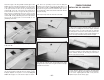
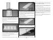
flush with each other. Slide former F-8B over the lower
gear supports. When satisfied with the fit, use 6-minute
epoxy to glue the assembly in the fuse.
❏ 21. From the remaining 3/8" x 1/2" basswood stick, cut
a 3" long tailgear rail. Use epoxy to glue the rail in the
notched lower gear supports.
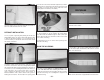
❏ 22. Carefully roughen the outside of the tail wheel
steering guide tubes with sandpaper. Insert and glue the
tubes in formers F-5 through F-8B.
❏ 23. Glue in the lower forward and aft 1/4" [6.4mm]
stringers. After the CA cures, sand the forward stringers
flush with F-2B and F-3B and the aft stringers flush with
F-6D through F-10B.
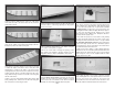
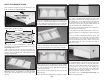
❏ 24. Use 30-minute epoxy to glue the shaped 1/4" x
1-3/8" x 5-15/16" plywood wing bolt plate into the
notches of the lower crutch. Also, from the 1/2" x 1/2" x
12" balsa triangle, cut and glue reinforcements to the joint
between the wing bolt plate and lower crutch.
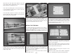
INSTALL THE FIREWALL
The following instructions will describe the procedure for
mounting a 41cc US Engine and Great Planes Large
Engine Isolation Mount. The installation procedure may
differ slightly if a different engine and engine mount are used.
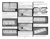
❏ 1. Use the template on the fuse plan to mark the
centerlines and the offset lines on the shaped 1/4" x
4-11/16" x 5-7/16" plywood firewall. The offset lines allow
for the right thrust of the engine.
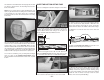
Option: If you are not using a Great Planes Isolation
Mount, skip to step 3.
❏ 2. Use the template on the fuse plan to mark the offset
line on the plywood isolation mount. If you will be installing
a US Engines 41, use the template to mark the mounting
hole locations on the isolation mount. If you are not
installing a US Engines 41, center the engine on the offset
lines and mark the mounting holes.
❏ 3. Align the offset lines on the isolation mount with the
offset lines on the firewall. Transfer the mounting hole
locations onto the firewall.
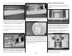
Option: If using a different type of engine mount, align the
centerline of the engine mount with the offset lines on the
firewall and mark the mounting holes.
❏ 4. Drill a 5/16" hole through the firewall at each
mounting hole location.
Option: For another engine mount, drill the appropriate
size hole, specified by the engine mount manufacturer.