™ DE MA IN A US WARRANTY.....Top Flite Models guarantees this kit to be free of defects in both material and workmanship at the date of purchase. This warranty does not cover any component parts damaged by use or modification. In no case shall Top Flite‘s liability exceed the original cost of the purchased kit. Further, Top Flite reserves the right to change or modify this warranty without notice.
TABLE OF CONTENTS INTRODUCTION . . . . . . . . . . . . . . . . . . . . . . . . . . . . . 3 PRECAUTIONS . . . . . . . . . . . . . . . . . . . . . . . . . . . . . . 3 DECISIONS YOU MUST MAKE. . . . . . . . . . . . . . . . . . 3 ENGINE SELECTION . . . . . . . . . . . . . . . . . . . . . . 3 RADIO SYSTEM REQUIREMENTS . . . . . . . . . . . 3 LANDING GEAR . . . . . . . . . . . . . . . . . . . . . . . . . . 3 SCALE COCKPIT INTERIOR . . . . . . . . . . . . . . . . 3 COMPETITION MINDED MODELERS . . . . . . . . . . .
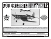
INTRODUCTION PRECAUTIONS Thank you for purchasing the Top Flite Gold Edition Giant F4U Corsair. Since this is a scale model with lots of detail, you’ll find it takes a little longer to complete than the sport models you’ve built before. But since this is a Top Flite Gold Edition kit, it is as easy to build as most sport models. The Top Flite Giant Corsair uses the same materials and standard construction techniques you’ve already become accustomed to.
The trim scheme of the Corsair on your kit box was inspired by the full scale “Bayou Baby”. The decal set included with the kit will allow you to quickly and easily duplicate the markings. If you prefer a different trim s c h e m e S c a l e M o d e l R e s e a rc h o f fe r s m a ny documentation packages as a guide.
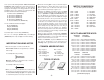
and replaceable Easy-Touch Adhesive-backed Sandpaper. While building the Giant F4U Corsair we used two 5-1/2" Bar Sanders and two 11" Bar Sanders equipped with 80-grit and 150-grit Adhesive-backed Sandpaper. Here’s the complete list of Easy-Touch Bar Sanders and Adhesive Backed Sandpaper.
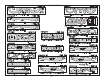
DIE-CUT PATTERNS -6-
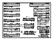
DIE-CUT PATTERNS -7-
(Continued from page 5.) 1/2" x 15/16" x 18" = 12.7mm x 23.8mm x 457.2mm 1/2" x 1" x 3" = 12.7mm x 25.4mm x 76.2mm 1/2" x 1-1/4" x 30" = 12.7mm x 31.8mm x 762.0mm 5/8" x 3/4" x 6" = 15.9mm x 19.0mm x 152.4mm 11/16" x 11/16" x 18" = 17.5mm x 17.5mm x 457.2mm Block Size in inches Block Size in millimeters 5/16" x 3/4" x 7/8" = 7.9mm x 19.0mm x 22.2mm 3/8" x 2" x 6" = 9.5mm x 50.8mm x 152.4mm 1/2" x 3" x 12" = 12.7mm x 76.2mm x 304.8mm 9/16" x 2" x 12" = 14.3mm x 50.8mm x 304.8mm 9/16" x 2-1/2" x 24" = 14.
❏ 2. Use 30-minute epoxy to glue the two die-cut 1/8" [3.2mm] plywood stab centers (SC) between the two 1/8" [3.2mm] balsa stab centers. To ensure that the lamination stays flat, clamp it to a flat table until the epoxy cures. ❏ E. Inspect the seam and press the sheets together where they do not align. ❏ 3. Use epoxy to glue the two shaped 1/4" [6.4mm] plywood leading edge doublers together. ❏ 6. From the remaining 1/2" x 7/8" balsa stick, cut and glue the stab tips to the LE. ❏ 7.
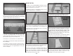
BUILD THE FIN ❏ 1. Make a left and right fin skin by cutting two 3/32" x 3" x 24" balsa sheets in half. Edge glue two sheets together to make two 6" x 12" sheets. ❏ 2. Place the fin plan on a flat building board. Cover the fin plan with plan protector or wax paper. ❏ 7. Position the fin over the fin plan. Mark the location of the top of formers F-8 and F-9 on both sides of the fin, . ❏ 10. Place one of the stab skins on your building board.
BUILD THE ELEVATORS ❏ ❏ 1. Place the die-cut 1/8" [3.2mm] balsa elevator base over the plan. Mark the locations of the “ribs” on both sides of the base. ❏ ❏ 2. From the grooved 11/16" x 11/16" x 18" balsa control surface LE, cut a piece to the length shown on the plan. ❏ ❏ 6. From the 1/8" x 1" x 30" balsa stick, cut and glue the balance tab base, centered on the LE of the elevator, at the location shown on the plan. ❏ ❏ 9. Cut a balance tab root cap rib from the remaining 1/8" x 1" balsa stick.
BUILD THE RUDDER ❏ ❏ 13. Use a razor plane and bar sander to shape the ribs to match the typical elevator cross-section shown on the plan. Note that there is some outward curvature of the ribs to provide the scale ribbed appearance. ❏ 14. Return to step 1 and build the second elevator the same way. ❏ 15. Use thick or medium CA to tack glue the elevators to the stab — just a drop in three or four places. Make sure to leave a 1/16" gap between the stab and the balance tab root rib.
❏ 6. Sand the LE of the balance tab base and ribs even. Cut a 3-1/2" long balance tab LE from the remaining 3/8" x 3/4" balsa stick. Glue the LE, centered on the front edge of the balance tab base and ribs. ❏ 7. Sand the bottom of the rudder even. Cut a root rib from the remaining 1/8" x 1" balsa stick and glue it, centered on the bottom of the rudder. ❏ 8. From the remaining 3/8" x 1-1/4" balsa block, cut a torque rod block to fit the opening in the rudder base.
BUILD THE WING rib locations on the aft LE. Glue the die-cut 1/4" [6.4mm] balsa forward center leading edge pieces together at the center. With the joints opposite each other, glue the aft LE, centered, on the forward LE. Do not apply glue to the forward LE between the embossed lines. BUILD THE WING CENTER SECTION NOTE: The wing root ribs are stamped only with a number (2 is R-2), the wing tip ribs are stamped with a T and a number (T4 is T-4). Note: On some of the die-cut 1/4" [6.
doubler. Remove any excess epoxy from the landing gear rail slots before the epoxy cures. ❏ 13. Glue the die-cut 1/8" [3.2mm] balsa forward ribs R-3 through R-5 in their respective locations, perpendicular to the center main spar. ❏ 17. From the remaining 1/2" x 7/8" balsa stick, make two 7/8" tall blocks to support the aft ends of ribs R-1A and to prevent the center section from twisting. Tack glue the blocks to the ribs. Pin the blocks to your building board and weight down the center section. ❏ 10.
BUILD THE WING TIP PANELS NOTE: The tip panels are built “UPSIDE-DOWN” on the wing plan (the jig tabs on the ribs are attached to what is, in the end, the TOP surface of the wing.) ❏ ❏ 1. Place the wing tip panel plan on a flat building board. Cover the plan with plan protector or wax paper. T-Pin ❏ 21. Insert a T-pin from the back of the LE, through the center of the 5/16" [7.9mm] holes in the wing dowel plate. Keep the T-pins perpendicular to the LE as you push them through.
JOIN THE WING PANELS HOW TO MAKE SERVO LEAD TUBES When the aileron servos are mounted near the wing tips, it can be difficult to route the servo wires through the ribs to the wing root. An easy solution is to make servo wire tubes. ❏ ❏ 9. Use a straightedge to draw lines on the LE and TE, from the bottom edge of rib T-6 to the bottom edge of rib T-7. Use a razor plane and sanding bar to taper the LE and TE. ❏ 1. Sand the center section LE to the approximate shape of the wing tip panels LE.
Top Spar Rib T-1 15/16" [23.8mm] 15/16" [23.8mm] Bottom Spar ❏ ❏ 4. On the wing tip panel, trim both the top and bottom spar 15/16" [23.8mm] from rib T-1. ❏ ❏ 5. With the embossed “tip” away from the rib, position the die-cut 1/8" [3.2mm] plywood wing spacer, next to the center main spar, against the center section rib R-1. Slide the wing tip panel onto the center main spar. You want the wing tip panel and wing center section to both fit against the spacer.
SHEET THE WING PANELS ❏ 1. Sort through the 3/32" x 3" x 30" balsa sheets, separating the best wood with the most uniform grain for the top wing skins. Use the remaining sheets for the bottom skins. 14" [355.6mm] 12" [304.8mm] 7" [177.8mm] 1-1/2" [38.1mm] 30" [762mm] 3" [76.2mm] ❏ 2. Make four outer wing panel skins using the method described for making the stab skins. Cut two 3/32" x 3" x 30" balsa sheets in half diagonally.
[3.2mm] plywood wing jigs under the wing tips at T-7 and the 1-1/4" x 1-3/4" x 3-1/4" balsa block under the wing center section TE. The wing tips must be seated on the wing jigs and the jigs against the building table in order to provide the proper amount of washout in the wing tips, when sheeted. Note: The wing jigs can be tack glued to the excess bottom sheeting, 1/16" [1.6mm] past rib T-7. ❏ 9. Before applying the top skin, rough cut the bottom skin from over the aileron hatch openings. ❏ ❏ 10.
❏ ❏ 18. When satisfied with the fit of the top TE skin, wet it again; apply medium or thick CA on ribs R-1 thorough R-4, the center spar and the TE between R-1 and R-5. Press the TE skin onto the structure and hold it in position until the CA cures. ❏ ❏ 19. After the CA cures, trim the top TE skin to the center of rib R-5 and flush with the TE. Glue the TE skin to rib R-5. between the servo hatch rails. This will provide a larger gluing surface for the bottom wing skins.
❏ 10. Sand the wing skin flush with the LE, TE and tip ribs R-7T. ❏ 11. Make two sets of 1-3/4" [44.5mm] thick wing tips by gluing two shaped 7/8" [22.3mm] balsa wing tips together. BUILD THE FUSELAGE BUILD THE UPPER FUSE SIDES ❏ ❏ 7. Cut a 3/32" [2.4mm] balsa skin to fit between ribs R-1 and R-3C. The first skin should cover the forward half of the main center spar. Wet the skin and glue it to the main spar and ribs starting at rib R-1. ❏ 1. Use 30-minute epoxy to glue the die-cut 1/8" [3.
❏ 3. Glue together the die-cut 1/8" [3.2mm] plywood formers F-6A to F-6B and F-7A to F-7B. Drill 3/16" [4.8mm] holes through the punch marks at the locations shown. ❏ 7. Pin the main fuselage stringers, with the 1/8" [3.2mm] slot facing outward, accurately over the plan. ❏ 10. After the epoxy cures, insert the die-cut 1/8" [3.2) plywood former F-2 into the slots in the crutch top and crutch. Position the assembly over the plan.
❏ 13. Insert the die-cut 1/8" [3.2mm] plywood formers F-3 and F-4 into their appropriate slots in the fuse crutch. Glue the formers to the crutch, crutch stringers and main fuse stringers. ❏ 14. Position the die-cut 1/8" [3.2mm] plywood formers F-5, F-6 and F-7 over the plan, perpendicular to the building board. Glue the formers to the crutch stringers and main fuse stringers. Use silicone glue to glue the retract air tank (not included) to formers F-4 and F-5.
Enlarge hole to 1/8" [3.2mm] Remove this pin ❏ 21. Use epoxy to glue the die-cut 1/8" [3.2mm] plywood former F-10 to the main fuse stringers and the lower aft fuse plate, perpendicular to the building board. Also use epoxy to glue the torque rod support plate to formers F-9 and F-10. ❏ 24. From the 1/4" x 1/4" x 30" balsa stick, cut and glue diagonal braces to the main stringers, between F-6 and F-7, F-7 and F-9 and F-9 and F-10.
❏ 33. Remove the T-pins holding the fuse to the building board. Use a sanding bar to blend the stringers with the formers, sanding any glue joints smooth that might affect the sheeting of the fuselage. ❏ ❏ 4. Use bright colored chalk to mark the top full length stringer. Wet the outside of the forward sheet and carefully wrap it around the formers, pressing it against the marked stringer. Trim the sheet so that it covers half of the top full length stringer.
36" [914.4mm] 1" [25.4mm] 11" [279.4mm] 6" [152.4mm] 3" [76.2mm] ❏ 8. Cut one 1/8" x 3" x 36" balsa aft sheet in half diagonally. Edge glue a full 1/8" x 3" x 36" balsa aft sheet and one diagonal sheet together. Make two aft sheets as shown in the sketch above. 3" [76.2mm] 30" [762mm] ❏ 11. From two 1/8" x 3" x 30" balsa sheets, cut a 1" x 11" [25.4 x 279.4mm] piece from one end of each sheet. Edge glue the 1" [25.4mm] piece to the other end of the sheet. sheets.
❏ 19. Tack glue the turtledeck top to the fuse being careful to not glue the fin in place. Remove the fin and thoroughly glue the turtledeck top to the fuse with thin CA. BUILD THE FUSE BOTTOM ❏ 1. Cut the three 36" [914.4mm] outer pushrod guide tubes to the lengths required for the rudder and elevator pushrods (see the fuse side view). ❏ 20. Shape the turtledeck top to match the cross-section on the plan. A razor plane is helpful for this kind of shaping. ❏ 2.
HOW TO ACHIEVE A GOOD SOLDER JOINT ❏ A. Roughen the area to be soldered with fine sandpaper. Thoroughly clean the area with rubbing alcohol. ❏ B. Assemble the items to be soldered. ❏ C. Apply a small drop of solder flux to the joint. ❏ 4. Install a high torque rudder servo in the radio tray. Connect the rudder servo and battery to the receiver, switch on the radio system and center the servo arm. Thread a 4-40 metal clevis onto a 4-40 x 36" threaded pushrod.
crutches to check that they fit together flush and the joints between the crutches are tight. Test fit the die-cut 1/8" plywood formers F-6C, F-3B and the crutch bottom (CB) on the lower fuse crutch. ❏ 15. When satisfied with the fit of the lower crutch, use 30-minute epoxy to glue the lower crutch to the upper crutch. Also use epoxy to glue F-3C, F-6C and the crutch bottom into position. Use plenty of clamps to hold the upper and lower crutches together until the epoxy cures. ❏ 11.
flush with each other. Slide former F-8B over the lower gear supports. When satisfied with the fit, use 6-minute epoxy to glue the assembly in the fuse. ❏ 21. From the remaining 3/8" x 1/2" basswood stick, cut a 3" long tailgear rail. Use epoxy to glue the rail in the notched lower gear supports. ❏ 22. Carefully roughen the outside of the tail wheel steering guide tubes with sandpaper. Insert and glue the tubes in formers F-5 through F-8B. ❏ 24.
❏ 5. Clean the 1/4-24 blind nuts with isopropyl alcohol and use epoxy to glue them into the mounting holes from the back of the firewall. SHEET THE BOTTOM OF THE FUSE ❏ 1. Use a sanding bar to blend the stringers to the formers. Option: If your engine mount comes with blind nuts, use epoxy to glue them into the mounting holes from the back of the firewall. If your engine mount uses a different mounting method, follow the manufacturers mounting instructions. ❏ 5.
❏ 9. Fit and glue a second lower fuse sheet to the other side. MOUNT THE WING ON THE FUSE ❏ 1. Set the wing in the wing saddle. Sand a slight radius on the LE of the center section to match the shape of the wing saddle. ❏ 10. Fit a third lower fuse sheet in place from the middle of the first stringer to the middle of the bottom stringer. Start by gluing the sheet at the center of the first stringer and working toward the ends.
❏ 11. After the epoxy cures, check that the wing is still centered on the fuse. Use weights to hold it firmly down. Use a 13/64" [5.2mm] drill bit to drill through the pilot holes in the tapered bolt plate and through the wing bolt plate in the fuse. ❏ 5. Use 3/32" x 3" x 24" balsa to sheet the bottom of the wing center section, between the R-5 ribs. ❏ 8. Tape the wing in position and cut a piece of 3/32" [2.4mm] balsa sheet to fit in the wing saddle behind the wing, flush with the fuse sides.
match the angle of the wing saddle. Carefully glue former W-6E to the top center wing sheeting. Do not glue it to the 1/16" [1.6mm] spacer. After the CA has cured, remove the 1/16" spacer. Glue the die-cut 1/8" [3.2mm] plywood former F-3C, to the LE of the wing, 1/32" (.8mm] aft of former F-3B. Be careful to not glue the wing to the fuse. After placing a straightedge along the notch in each former, align and glue the die-cut 1/8" [3.2mm] plywood former F-4C, 5-7/8" [149.
been die-cut for the wheel well and require that you finish cutting them. The full size Corsair did not have wheel well liners. But, if you prefer, liners can be made from 1/16" [1.6mm] plywood or balsa (not included). ❏ ❏ 2. Remove the aileron LE from the wing and mark a centerline on the surface. ❏ 4. Use leftover 1/2" x 1/2" balsa hinge block material to fair in the outboard ends of the oil coolers. RETRACT INSTALLATION ❏ 1.
❏ ❏ 5. Cut aileron “ribs” from the 1/8" x 1/2" x 30" balsa sticks. Glue the ribs to the aileron base at the previously marked rib locations. ❏ ❏ 6. From the 1/2" x 1/2" [12.7mm x 12.7mm] balsa stick, cut 3/4" [19mm ) long hinge point backups. Glue the backups in position as shown on the plan. ❏ ❏ 10. Insert the hinge points in the TE of the wing and test fit the aileron on the wing, adjusting the hinge point holes as necessary. ❏ ❏ 11.
❏ ❏ 22. Cut a recess for the control horn plate on the other side of the aileron. BUILD THE OUTBOARD FLAPS ❏ ❏ 23. Use epoxy to glue the control horn plates to the ailerons. ❏ ❏ 1. From a 1/2" x 15/16" x 18" balsa stick, cut a 9" [228.6mm] long outboard flap LE. Save the remaining piece for the inboard flap. 8-7/8" [225.4mm] 3" [76.2mm] ❏ ❏ 24. Thread a 4-40 nut onto a 4-40 x 12" [4-40 x 304.8mm] threaded pushrod.
the previously marked hinge locations. These holes should angle slightly toward the center of the wing. See the flap detail on the wing plan. ❏ ❏ 14. With the ailerons temporarily mounted on the wing, tack glue a leftover piece of 1/16" [1.6mm] plywood to the inboard end of the aileron. Remove ❏ ❏ 10. Glue the die-cut 1/8" [3.2mm] plywood flap ends to the ends of the outboard flaps, aligning the front of the plywood flap end and the LE. The flap end with the two punch marks goes on the inboard end.
BUILD THE INBOARD FLAPS ❏ ❏ 1. From the remaining 1/2" x 15/16" balsa stick, cut a 6-7/8" [174.6mm] long inboard flap LE. ❏ ❏ 6. Use a sanding bar to bevel the short edge of the inboard LE so that it fits tightly against the forward edge of the ribs and flap skin. The LE will hang over the forward edge of the flap skin. When satisfied with the fit, glue it in position. ❏ ❏ 2. Sand one end of the stick to match the contour of the belly pan at the TE of the wing. ❏ ❏ 13.
BUILD THE MIDDLE FLAPS ❏ ❏ 4. Position the middle flap LE over the plan and mark the rib locations. ❏ ❏ 1. Glue two of the die-cut 1/4" [6.4mm] balsa middle flap LE’s together to make a 1/2" [12.7mm] thick flap LE. ❏ ❏ 7. From the 1/2" x 1/2" balsa stick, cut 3/4" [19mm] long hinge point backups and flap torque rod blocks. Glue the blocks on the back of the LE, end ribs and bottom skin. Sand the flap torque rod blocks flush with the end ribs. ❏ ❏ 5.
INSTALL THE FLAP CONTROLS ❏ ❏ 11. Use a sanding bar to sand the LE and flap skins flush with the plywood flap ends. outline of the hatch onto the wing skin and carefully cut out the bay, fitting the hatch into place. ❏ ❏ 1. Cut 4" [101.6mm] from the non-threaded end of two 4-40 x 12" [304.8mm] threaded pushrods. Cut both 4" [101.6mm] pushrods in half. Temporarily install a 2" [50.8mm] flap torque rod in each end of the middle flap. The rods should protrude out approximately 1" [25.
flap servo so that the arm is in the forward position and mark the servo arm location on the bottom of the wing. ❏ ❏ 8. Position a straightedge along the mark on the top of the flap servo hatch. Mark the TE of the wing at the location for the flap pushrod exit. Note: One of the pushrods will need to be angled slightly to avoid the flap hinge. ❏ ❏ 12. Cut a slot 1/4" [6.4mm] from the top of the flap, at the mark made in step 10 on the inboard flap LE.
FINISH THE FUSELAGE MOUNT THE STABILIZER 1-1/16" [27.0mm] ❏ 4. Thread a nylon torque rod horn onto each elevator torque rod so that the center of the torque rod horn is 1-1/16" from the center of the bend. It’s important that both horns are the same distance from the center of the bend. ❏ 1. Sand the LE of the stab so that the TE of the stab is flush with the aft edge of former F-10. ❏ 5.
system and center the servo arms. Thread 4-40 metal clevises 14 turns onto two 4-40 x 48" [121.9cm] threaded pushrods. Insert the pushrods into the elevator outer pushrod tubes and connect the clevises to the servo arms on the elevator servos. FINISH THE FUSE AFT END ❏ 1. Sand the side sheeting flush with the aft edge of former F-12. Trim the jig tab from the bottom of former F-12. Taper the fuse side sheeting between F-11 and F-12 as shown on the fuse plan.
❏ 6. Move the rudder torque rod through its range of motion. Make sure it is at an elevation where it is not binding or striking a former. Position the rudder on the fin and mark the location on the LE of the rudder where the rudder torque rod will be inserted. ❏ 7. Drill a 5/32" [4mm] hole into the rudder perpendicular to the LE, at the mark for the torque rod. Make a slot in the rudder LE large enough to clear the torque rod and bearing tube, from the 5/32" [4mm] hole to the bottom of the rudder. ❏ 8.
FIT THE RETRACTABLE TAILGEAR INSTALL THE ENGINE The following instructions are for mounting the US Engines 41cc on the Great Planes Isolation Mount. If you are installing a different engine and engine mount, follow the instructions included with the engine and engine mount. Note: You previously prepared the firewall for engine installation, before gluing the firewall on the fuse. ❏ 4. On the US Engines 41, we moved the throttle connector arm to the other arm on the bellcrank.
❏ 6. Install a 2-56 pivot ball on the throttle bellcrank. Snap a ball end onto the pivot ball. Mark the isolation plate in line with the ball end and drill a 3/16" [4.8mm] hole at the mark through the plate and firewall. If you don’t have a long 3/16" [4.8mm] drill bit you may need to remove the engine to drill the holes. ❏ 7. Roughen a 3/16" [4.8mm] outer pushrod tube with 320 grit sandpaper. Glue the outer pushrod tube in the 3/16" hole in the firewall, flush with the front of the firewall.
❏ 2. Use your bar sander to carefully true the edge of the overlaps so when you glue them together the seam will be as small and straight as possible. Sand all four pieces, inside and out, with 320-grit sandpaper. Wash the cowl pieces with soap and water and dry thoroughly. ❏ 6. Glue fiberglass behind the mounting holes and along the seams on the inside of the cowl. For maximum protection against stress cracks, you may apply 3/4oz. fiberglass cloth to the entire inside surface of the cowl.
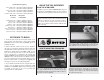
FINISHING BALANCE THE MODEL LATERALLY Do not confuse this procedure with “checking the C.G.” that will be discussed later in the manual. Now that the model is nearly completed, you should balance it laterally (side-to-side). An airplane that is laterally balanced will track better. Here’s how: ❏ 1. Temporarily attach the elevators, rudder, engine, cowl, landing gear and wing. Lift the model by the propeller shaft and the bottom of the fuse near the rudder. This will require an assistant.
Trim the MonoKote covering at the edge of the oil coolers. Apply a thin coat of filler along the edge of the MonoKote covering. After the filler dries, sand it flush with the covering. Use masking tape to mask off the area around the oil coolers. Spray a couple of coats of primer over the oil cooler and filler. After the primer dries, remove the masking and sand the primer to blend it into the covering. Carefully paint the oil cooler and filler with LustreKote paint.
❏ 8. Connect the elevator, rudder, aileron, flap and throttle pushrods to the servo arms. ATTACH THE CANOPY COOLING NOTES ❏ 9. If you installed a gas engine, install an on/off switch on the engine that can be manually turned off from the outside of the cowl. Also an engine on/off switch must be installed that can be operated from the transmitter. This can be activated by a separate switch on the transmitter or by the engine cut switch, found on some transmitters. ❏ 1.
Most modern engines in the size range specified provided more than ample power for the Corsair. It is recommended, therefore, that you run the engine somewhat rich for the first flights because the excess fuel running through the engine provides a cooling effect. If your engine is not broken in, run a few tanks of fuel through it on the ground with the cowl removed before flying. Note: The balance and control throws for the Giant Corsair have been extensively tested.
Note: Because of the large engines that are used on giant airplanes and the difference in their weights, it is not uncommon to add 1 lbs to 3 lbs of weight to the nose of the models. PREFLIGHT At this time check all connections including servo horn screws, clevises, servo cords and extensions. Make sure you have installed the nylon retainer on the ScrewLock Pushrod Connector and the silicone retainers on all the clevises.
ENGINE SAFETY PRECAUTIONS Note: Failure to follow these safety precautions may result in severe injury to yourself and others. Keep all engine fuel in a safe place, away from high heat, sparks or flames, as fuel is very flammable. Do not smoke near the engine or fuel; and remember that the engine exhaust gives off a great deal of deadly carbon monoxide. Do not run the engine in a closed room or garage. Get help from an experienced pilot when learning to operate engines.
5.3 There must also be a means to stop the engine from the transmitter. The most common method is to close the carburetor throat completely using throttle trim, however, other methods are acceptable. This requirement applies to all glow/gas ignition engines regardless of size. Section 6.0: RADIO REQUIREMENTS 6.1 All transmitters must be FCC type certified. 6.2 FCC Technician or higher-class license required for 6 meter band operation only.
FLIGHT We recommend that you take it easy with your Corsair for the first several flights, gradually “getting acquainted” with this great model as your engine gets fully broken in. If you feel as though you have your hands full, keep this in mind: pull back on the throttle stick to slow the model down. This will make everything happen a little slower and allow yourself time to think and react. Add and practice one maneuver at a time, learning how the Corsair behaves in each.
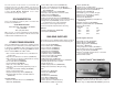
Top Flite® 1/5 Giant Scale Gold Edition™ Top Flite® 1/5 Giant Scale Gold Edition™ P–47D Thunderbolt TOPA0415 P–51D Mustang TOPA0400 Giant “Jug” — with big advantages for builders! Build and fly your own giant–scale warbird! Wingspan: 85 in (2160mm) Wing Area: 1327 sq in (85.6 sq dm) Weight: 20-22 lb (9.07-9.98kg) Wing Loading: 34.7-38.2 oz/sq ft (106-117 g/sq dm) Fuselage Length: 75.5 in (1917mm) Requires: 6-7 channel radio w/5 high-torque and 4-6 std servos, 2.1-2.
Top Flite® Giant Scale F4U Corsair DLE™ Engines DLE-55cc Gas Engine Cockpit Interior Kit (TOPQ8407) Enrich the scale detail and realism of your Giant Scale Gold Edition F4U Corsair! This kit installs easily and comes with seat, laser cut instrument panel and other components for outstanding authenticity. Includes decals (paint available separately). Premium gas performance! Output: 5.