
User manual Stinson Reliant SR9 (1/5)


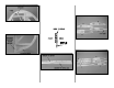


❏ 9. Insert a 1/16" balsa spacer between the rudder
tip and fin rib V6. Hold the r udder tip to the fin with a
T-pin. Shape the rudder tip as shown on the plan to
match the rudder and fin.
Now you may separate the r udder from the fin.
❏ 10. Make the rudder control horn blocks for
both sides of the rudder from the remainder of the
5/8" x 5/8" bass wood stick. Make the rudder base for
both sides of the rudder from the 3/8" x 1/2" x 12"
balsa stick. Tr im the bottom cap strip and the rudder
edging to accommodate the rudder base, then glue
the rudder bases to the rudder. Trim, then sand the
rudder control horn blocks and the rudder bases to
blend with the rudder, but do not round or final shape
until instructed to do so (when it’s time to match the
rudder to the bottom of the fuse).
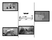
❏ 11. Hinge the rudder and fin the same as you did
the stab and elevators. Bevel the leading edge of the
rudder to allow for control throw. Be cer tain you can
achieve 2" control throw in both directions.
BUILD THE WING
Preliminary assembly
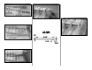
❏❏1. When removing ribs from die-cut sheets,
save the 1-1/8" round plug from both r ib 10’s.
Build the left wing panel first so yours matches
the photos.
❏❏2. Glue together two die-cut 1/8" balsa inner TE
spars with the notches in alignment. Securely, but
temporarily, tack-glue the die-cut 1/8" balsa inner
TE spar jig to the bottom of the inner TE spar along
the aft edge. The jig will suppor t the inner TE dur ing
construction, but will be remov ed after the wing panel
is removed from the building board.
❏❏3. Cut along the partially die-cut line of one die-
cut 1/8" balsa outer TE spars and remove the jig.
Glue that outer TE spar to the front of another outer
TE spar that has the jig still attached.
❏❏4. Working over Great Planes Plan Protector,
glue together the die-cut 3/32" balsa pieces that
make up ribs W4, 5, 6 and 7. Note: Be certain to
leave a 1/4" gap between W7B M and W7B R.
❏❏5. Glue the die-cut 1/8" balsa rib doublers to ribs
4 and 6 and the die-cut 1/8" plywood rib doublers to
ribs 1, 2, 3, 5 and 7. Refer to the plan to see which side
of the ribs the respective doublers are glued to (the
doublers go on the outside of all ribs except rib 7).
- 17 -