
User manual Cessna 182

1. Unroll the plan sheets. Re-roll the plans
inside-out to make them lie flat.
2. Remove all parts from the box. As you do, fig-
ure out the name of each part by comparing it
with the plans and the parts list included with this
kit. Using a felt tip or ball point pen, lightly write
the part name or size on each piece to avoid
confusion later. Use the die-cut patterns shown
on pages 7 and 8 to identify the die-cut parts and
mark them before removing them from the
sheet. Save all scraps. If any of the die-cut parts
are difficult to punch out, do not force them!
Instead, cut around the parts with a hobby knife.
After punching out the die-cut parts, use your T-
Bar or sanding block to lightly sand the edges to
remove any die-cutting irregularities.
3. As you identify and mark the parts, separate
them into groups, such as fuse (fuselage), wing,
fin, stab (stabilizer), and hardware.
1. Work on a flat surface over the plans covered
with waxed paper. Refer to the plans to identify
the parts and their locations.
The plans may be
cut apart if space is a problem.
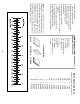
2. Punch out both sets of the die-cut 3/32” balsa
ribs S-1 through S-7. There is a jig tab on the
bottom edge of each of these ribs. If any of
these break off, carefully glue them back on with
a drop of thin CA. Lightly sand any imperfec-
tions. You may need to finish cutting the notch in
the forward portion of S-1 for the Stab Joiner
(SJ) with a knife. Use a pen to mark the exten-
sions of the bottom edge of the ribs across the
fore and aft ends of the jig tabs. These marks
will help when you trim off the jig tabs later.
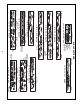
3. The stab Trailing Edges (S) are die-cut from
1/4” balsa. Since some crushing may occur dur-
ing die-cutting wood of this thickness, they are
supplied slightly long and can be trimmed. True
up all edges of these pieces with a T-bar.
❏❏4. Cut the stab Leading Edges (LE’s) to
length from the 1/4” x 15” tapered balsa stock.
They should be about 1/4” longer than the length
shown on the plans for the stab LE.
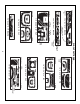
❏❏5. Center the 1/2” x 5/8” x 9-3/4” balsa TE
Center Brace over the plans and pin it in place.
Use a triangle and pen to mark the inboard ends
of the Stab TE. Remove the TE Center Brace
from the building board.
❏❏6. Apply thick CA to one half of the TE
Center Brace, then align the inboard end of a
Stab TE with the reference line you just drew.
Glue the TE Center Brace in position. The TE
Center Brace must be centered on the Stab
TE. Repeat this operation for the other half of
the TE, then use long T-pins to pin the assembly
over the plans.
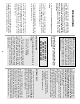
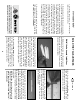
NOTE: Position the outboard ends of the
TE about 1/2” above the board. The TE
Center Brace should be raised about 3/8”.
(See next photo.)
FIN / STAB LE
Build the horizontal stabilizer
BUILD THE TAIL SURFACES
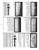
Zipper-top food storage bags are a handy
way to store your small parts as you sort, iden-
tify, and separate them into sub-assemblies.
Get ready to build
9