
User manual Cessna 182

When everything is locked in place, glue the
assembly together. The 3/16” side stringers may
now be trimmed flush with the forward edge
of F-1.
❏ 12. Lightly sand the outside of the two 36”
outer pushrod tubes then insert them through
the holes in F-2 through F-8. Trim the tubes so
that 1/4” protrudes past F-2 and F-8. Apply a
drop of medium CA to the pushrod tubes at each
former except F-2.
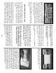
❏ 13. Use 30-Minute Epoxy to glue the 1/4”
birch ply Landing Gear Plate between former
LF and F-3. Be sure that the notches fit well and
that the Landing Gear Plate is firmly against the
Keel.
While the epoxy cures there are a few
other parts we can work on.
❏ 14. Cut two 3/16" stringers from the 24"
lengths provided, to fit from F-2 to F-4 in the
first set of notches above the Main Stringer.
Glue them in place, then sand the ends flush
with the formers.
❏ 15. Glue the 1/8” die-cut ply Nose Gear
Doubler to the aft side of F-1. Be sure to align
the stringer notches.
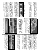
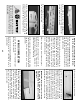
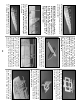
❏ 16. Center the nylon Nose Gear Bearing on
the tapered 1-1/4” x 1-5/8” basswood Nose
Gear Block. Mark the mounting holes in the
Nose Gear Block, then drill the holes with a 1/8”
bit. Drill the four index marks on the forward
side of F-1 with a 5/32” bit.
❏ 17. Install the Nose Gear Bearing/Block on
F-1 with four 4-40 x 1” Pan Head Bolts and four
4-40 Blind Nuts. The wide end of the Nose Gear
Block points away from the building board.
Drill out the Nose Gear Wire Hole with a 13/64”
drill bit. Remove the Nose Gear Bearing/Block
then use thick CA to mount the basswood block
permanently to F-1. Be sure that all of the
mounting holes stay in alignment.
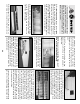
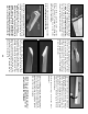
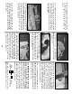
❏ 18. After the epoxy on the 1/4” Landing Gear
Plate has fully cured (
an hour or more
) clamp
both of the bent aluminum Main Landing Gear
struts in position. The struts should touch the
Keel and F-3. Use a 9/64” drill bit to drill through
the mounting holes in the struts and also
through the Landing Gear Plate. Enlarge the
holes in only the plywood Landing Gear Plate
with an 11/64” (or 3/16”) drill bit to provide
clearance for the 8-32 mounting bolts.
❏ 19. Use an 8-32 Tap to cut threads in the
aluminum Main Landing Gear mounting holes as
well as the axle mounting holes. Temporarily
install the Landing Gear in the fuse with six 8-32
x 1/2” socket head cap screws.
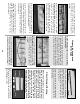
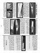
❏ 20. IMPORTANT: Before you do this step,
make certain that the Main Stringers are
pinned or weighted FLAT onto the building
surface. Cut and install all the remaining 3/16”
square stringers for the fuse bottom. Check each
former for twists and the correct angle before
you use glue. Use the Former Angle Template
as you proceed. The inside ends of the center
stringer should be sanded for a flush fit, then
butt glued to the ends of the Keel.
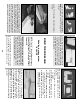
❏ 21. Glue two of the four 1/8” x 3/16” x 24”
Main Sub-Stringers into the groove in one of
MAIN
SUB-STRINGERSTRINGER
MAIN
30