INSTRUCTION MANUAL Top Flite Models Champaign, IL Telephone (217) 398-8970, Ext. 5 airsupport@top-flite.com WARRANTY SPECIFICATIONS Top Flite Models guarantees this kit to be free from defects in both material and workmanship at the date of purchase. This warranty does not cover any component parts damaged by use or modification. In no case shall Top Flite’s liability exceed the original cost of the purchased kit. Further, Top Flite reserves the right to change or modify this warranty without notice.
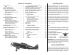
TABLE OF CONTENTS INTRODUCTION . . . . . . . . . . . . . . . . . . . . . . . . . . 2 AMA . . . . . . . . . . . . . . . . . . . . . . . . . . . . . . . . . 2 SCALE COMPETITION . . . . . . . . . . . . . . . . . . . . . 2 SAFETY PRECAUTIONS. . . . . . . . . . . . . . . . . . . . 3 DECISIONS YOU MUST MAKE . . . . . . . . . . . . . . . 3 Engine Recommendations. . . . . . . . . . . . . . . . 3 Electric Motor Recommendations . . . . . . . . . . 3 Radio Equipment . . . . . . . . . . . . . . . . . . . . . . . 3 S.
the Fun Scale class in AMA competition (we receive many favorable reports of Top Flite ARFs in scale competition!). In Fun Scale, the “builder of the model” rule does not apply. To receive the five points for scale documentation, the only proof required that a full size aircraft of this type in this paint/markings scheme did exist is a single sheet such as a kit box cover from a plastic model, a photo, or a profile painting, etc.
The Giant P-47 Razorback ARF requires a servo to operate the air control valve if using pneumatic retracts, a throttle servo, two flap servos, two aileron servos, two elevator servos and a rudder servo. Servos with a minimum of 50 oz-in [3.9kg-cm] of torque are required for operating the elevators, rudder, ailerons and flaps. We recommend that metal geared servos also be used. Standard servos may be used for the throttle and choke (the servo operated choke is optional).
Many servo choices are available for use in a wide variety and sizes of aircraft from micros to the largest models. HOW DO YOU INSTALL THE S.BUS SYSTEM? Installation is actually simplified as compared to your normal system installation. Using the S.Bus system you plug a battery into the SBC-1 channel changing tool, using it to program which channel you want the servo to operate on. Once programmed the ser vo will operate as required regardless of which lead it is plugged into.
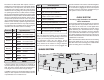
ADDITIONAL ITEMS REQUIRED REQUIRED HARDWARE AND ACCESSORIES In addition to the items listed in the “Decisions You Must Make” section, following is the list of hardware and accessories required to finish the Top Flite Giant P-47 Razorback ARF. Order numbers are provided in parentheses.
ORDERING REPLACEMENT PARTS Replacement parts for the Top Flite Giant P-47 Razorback ARF are available using the order numbers in the Replacement Parts List that follows. The fastest, most economical service can be provided by your hobby dealer or mail-order company. Not all parts are available separately (an aileron cannot be purchased separately, but is only available with the wing kit).
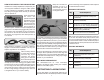
ASSEMBLE THE WINGS HINGE THE AILERONS Start with the left wing so the assembly matches the photos the first time through. ❏ 1. Pull on the ailerons and elevators, making sure the hinges are secure. The P-47 had many attributes that led to its reputation. One of the most important was its durability in combat. Oftentimes the P-47 would bring pilots home with missing cylinders, blown-off wing tips and large portions of tail surfaces missing. The P-47’s internal systems were very durable and well protected.
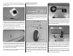
metal screws to secure the servo mounting blocks to the aileron servo hatch. Use thin CA to harden the screw threads. MOUNT THE RETRACTS Install the left retract first. ❏ ❏ 1. Use a hex wrench to loosen the strut mounting bolt and remove the strut. Slide two aluminum landing gear door mounts onto the strut and reinstall the strut in the strut mount. ❏ ❏ 3. Test fit the retract unit with the wheel into the wing. Position the retract so the wheel is centered in the wheel well.
❏ ❏ 6. Hold the retract in the wing. Using the mounting ❏ ❏ 9. Set the retract cover over the retract and drill holes as a guide, drill 7/64" [2.8mm] pilot holes into the retract rails. Caution: Do not inadvertently drill into the electric actuator when you get to the middle hole. Mount the retracts with five #6 x 3/4" [19.1mm] sheet metal screws, one in each corner and one in the middle as shown. Use one #6 x 1/2" [12.7mm] sheet metal screw in the hole over the electric actuator. a 1/16" [1.
INSTALL THE FLAP SERVOS the aileron servo arm 5/8" [15.9mm] from the center of the arm. HOW TO SOLDER 1. Use denatured alcohol or other solvent to thoroughly clean the pushrod. Roughen the end of the pushrod with coarse sandpaper where it is to be soldered. ❏ ❏ 1. Install the flap servos following the same procedure used to install the aileron servos. Note that the flap servos face the same direction. ❏ ❏ 2. Connect a 12" [305mm] servo extension wire to the flap servo.
The Thunderbolt was a massive airplane, the biggest and heaviest single engine, single-place fighter ever built. The engine, the Pratt & Whitney 18 cylinder twin-row radial, developed 2,000 HP and was the most powerful engine at the time. However, in turn, it needed a highly efficient duct system for its super-charger. The designer, Alexander Kartvile, designed the duct system first, then built the fuselage around it. ❏ ❏ 4. Slide a silicone clevis retainer over the solder clevis.
together with rubberbands around the wing dowels and the trailing edge. Clean the tubes with denatured alcohol and insert both tubes back into the fuselage until the end exits on the opposite side by approximately 1" [25.4mm]. ❏ 5. Remove the rubberbands and separate the wing halves. Remove the wing joiner. Mix 2 oz. [59.1cc] of 30-minute epoxy. Working quickly, pour a generous amount into the joiner pocket of one wing half.
is too much resistance, or if you are not able to move the rudder left and right 2" [50.8mm], widen the gap slightly between the rudder and the fin. ❏ ❏ 6. Remove the rudder and all the hinges. Add a small drop of oil to the pivot point on the hinges. This will prevent the epoxy from adhering to the pivot point. Make sure oil does not get on the gluing surface of the hinge. If it does, clean the oil off with a paper towel square dampened with denatured alcohol.
❏ 4. Enlarge the middle hole in both sides of the steering arm with a 3/32" [2.4mm] drill. Insert a 2-56 ball link ball in the hole. Secure each ball with a 2-56 nut and a drop of threadlocker. ❏ 8. Now pull on the long end of the cable to reduce the size of the first loop. Slip the loop over one of the ball link balls on the steering arm. Tighten the loop until it is small enough to remain secure on the ball, yet may still be pried off. Squeeze the swage with pliers.
INSTALL THE ELEVATOR & RUDDER SERVOS ❏ 3. Mount the control horns to the elevators and the rudder. Follow the same procedure used for the ailerons, by drilling 3/32" [2.4mm] holes and using #4 x ❏ 1. Hold your engine, inverted, up to the firewall. 1/2" [12.7mm] sheet metal screws. Attach the elevator Determine which side the throttle and choke is on. clevis in the third hole from base of the control horn.
Overlap by 1" (25.4 mm) a 6" (152 mm) long piece of hook and loop material. Route the hook and loop material through the two slots in the forward fuselage on the same side as the rudder servo. Wrap the receiver battery in R/C foam rubber and secure it to the side of the fuselage with the hook and loop material. Connect the receiver battery to the receiver switch. Use the included heat shrink material to secure the connectors. Make sure the receiver battery is secure. ❏ 10.
it as shown. Apply thread locker to the screw before reinstalling it. ❏ 5. Temporarily install the engine inverted on the aluminum standoffs. ❏ 9. Glue the forward fuel tank support to the firewall, aligning the embossed arrows. The edge of the tank support should align with the two slots. ❏ 6. Snap a nylon ball socket onto both pivot balls. ❏ 3. Install the engine mounting bolts and fender Center the choke and throttle arms and mark the firewall where the pushrods will need to pass through.
❏ 11. Mount the throttle servo in the servo tray and ❏ 13. Glue the plywood pushrod support so that the ❏ 15. Position the throttle stick so that it is centered slide a plywood pushrod support onto the outer pushrod tube. pushrod is inline with the servo arm and on the outside of the aft fuel tank support. on the transmitter. Adjust the throttle servo arm so that it is centered on the throttle servo. Move the throttle arm on the carburetor so that the throttle is open approximately half way.
excess wire can be secured with a piece of rubber band (not included) glued to the firewall box. ❏ 20. Wrap the ignition battery in R/C foam rubber and attach it to the bottom of the firewall box with hook and loop material. Install the ignition switch in the side of the fuselage at the front. ❏ 17. Trim approximately 1/8" (3.2 mm) from the end of the nylon ball socket before threading the 2-56 x 1" ( 25.4 mm) threaded rod into the end. Also trim 3/8" (9.5 mm) from the end of the threaded rod.
ELECTRIC MOTOR INSTALLATION ❏ 3. Glue the aft battery tray support to the battery tray and the fuselage sides. ❏ 1. The removable battery hatch is secured at the factory with four #2 x 3/8" (9.5 mm) sheet metal screws. Remove the four screws from the inside of the fuselage. Using a sharp knife blade, locate and carefully cut the battery hatch from the fuselage. Extra Olive Drab covering has been provided to cover the edges of the hatch and the fuselage along the cut. ❏ 4.
❏ 6. Follow the Stand Off Motor Mount instructions to install the motor on the firewall box. The RimFire 65 motor uses the embossed ‘X’ pattern on the front of the firewall box. Drill a 5/16" [8mm] hole at each mark. ❏ 7. Assemble the ESC mount as shown. Drill 5/64" ( 2 mm) pilot holes through the doubler as shown. ❏ 8. Position the ESC mount on the firewall box and drill four 5/64" (2 mm) pilot holes through the firewall box. (Two on top and two in the front.) Attach the ESC mount with #4 x ½" (12.
a 1/16" (1.6 mm) pilot hole in the servo tray using the four mounting holes in the retract servo tray as guides. Attach the retract servo tray with #2 x 3/8" (9.5 mm) sheet metal screws and #2 flat washers. ❏ 2. Install the retract control valve servo in the retract servo tray and plug it into the receiver. ❏ 9. Attach the ESC to the ESC mount with four #4 x ½" sheet metal screws and #4 flat washers.
Drill a 1/16" [1.6mm] hole through the forward former using the hole in the cowl mounting bracket as a guide. Attach the cowl mounting bracket to the forward former using 6-minute epoxy, #2 x 3/8" [9.5mm] sheet metal screws and #2 flat washers. INSTALL THE TAIL GEAR COVER ❏ 1. Operate the tail gear retract a couple of times, making any adjustments as needed. The opening for the tail gear may need to be widened slightly at the steering arm to prevent the steering arm from rubbing on the fuselage.
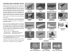
❏ 6. The plywood engine frame can be painted black. ❏ 10. Drill 1/8" (3.2 mm) holes in the bottom of the Use 6-minute epoxy to glue the plastic radial engine ❏ 12. The plywood engine frame can be painted black. rocker arms and in the crankcase as shown. Glue the to the plywood engine frame. Align the radial engine with the embossed circle on the plywood frame. ❏ 7. Enlarge the hole in the plywood frame to match eighteen aluminum tubes in the holes.
in the cowl. It should fit over the rocker arm covers of the radial engine, against the inner lip of the cowl. Once satisfied with the fit, use medium sandpaper to roughen the end of the intake. Clean the sanding dust off with denatured alcohol and glue it to the cowl inside with CA. Use canopy glue to attach the front of the intake to the back of the cowl lip. ❏ 19. Route the vent fuel line from the fuel tank out the exhaust exit in the bottom of the cowl. APPLY THE FINAL DETAILS ❏ 14.
❏ 3. Glue the two oil cooler louvers to the forward ❏ 5. Insert one of the red round headed pins in the ❏ 6. Trim the sides of the cockpit leaving approximately lower fuselage following the same procedure used to install the turbocharger exhaust fairing. lower right corner of the instrument panel to represent a knob. Glue the instrument panel in the front of the cockpit so that the top of the instrument panel is flush with the top of the fuselage.
FINISH THE WING ❏ 5. Glue the belly pan to the wing using 30-minute ❏ 8. Now is the time to securely install a pilot before gluing the canopy on. The pilot used is from Best Pilots. Wash the canopy in warm water, and then, dry it off. Place the canopy on the fuselage. Be certain it is centered from side-to-side and mark the outline on the fuselage. As before, prick holes in the covering just inside the outline. Use canopy glue to attach the canopy on the fuselage. epoxy.
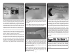
6-minute epoxy. Note the distance from the leading edge of the wing to the end of each gun barrel. ❏ 8. Test fit the belly pan on the wing attaching it with four ¼"- 20 x 2" ( 51mm) nylon wing bolts. The “belly pan” under the wing conceals the air ducting for the supercharger. One duct carries air from the intake in the front of the cowl back to the supercharger (driven by the turbine) and two smaller ducts carry exhaust gasses from the engine to the turbine. APPLY THE DECALS ❏ 1.
the model. Not only will engine mounting bolts loosen, possibly with disastrous effect, but vibration may also damage the receiver and receiver batteries. Vibration can also cause the fuel to foam, which will, in turn, cause the engine to run hot and quit. (Electric Motor) We use a Top Flite Precision Magnetic Prop Balancer (TOPQ5700) in the workshop and keep a Great Planes Fingertip Prop Balancer (GPMQ5000) in our flight box. ❏ 4.
❏ 2. If one wing always drops when you lift the model, SET THE CONTROL THROWS it means that side is heavy. Balance the airplane by adding weight to the other wing tip. An airplane that has been laterally balanced will track better in loops and other maneuvers. CHECK THE CONTROL DIRECTIONS ❏ 1. Turn on the transmitter and receiver and center the trims. If necessary, remove the servo arms from the servos and reposition them so they are centered. Reinstall the screws that hold on the servo arms. ❏ 6.
ruler forward so it will remain contacting the trailing edge. The distance the elevator moves up from center is the “up” elevator throw. Measure the down elevator throw the same way. If your radio does not have dual rates, we recommend setting the throws at the high rate settings. NOTE: The throws are measured at the widest part of the elevators, rudder and ailerons.
This is where your model should balance for the first flights. Later, you may experiment by shifting the C.G. 1/4” [6.4mm] forward or 1/4” [6.4mm] back to change the flying characteristics. Moving the C.G. forward will improve the smoothness and stability, but the model will then be less aerobatic (which may be fine for less-experienced pilots). Moving the C.G. aft makes the model more maneuverable and aerobatic for experienced pilots.
GROUND CHECK AND RANGE CHECK The final variant of the P-47 was the P-47N-25 rolling off the Republic Farmingdale production line in 1945. The “N” featured squared-off clipped wing tips and an increased wingspan to accommodate four additional 50-gallon internal wing tanks. The goal of increasing range to fulfill the roll of bomber escort (and to become more competitive with the P-51 Mustang) was accomplished.
NEVER disassemble or modify the pack wiring in any way or puncture the cells. Note: This does not apply to models while being flown indoors. NEVER discharge LiPo batteries below 2.7V per cell. 7) I will not operate models with pyrotechnics (any device NEVER place the battery or charger on combustible materials or leave it unattended during charge or discharge. that explodes, burns, or propels a projectile of any kind). RADIO CONTROL ALWAYS KEEP OUT OF THE REACH OF CHILDREN.
Remember to takeoff into the wind. When you’re ready, point the model straight down the runway, hold a bit of up elevator to keep the tail on the ground to maintain tail wheel steering, then gradually advance the throttle. As the model gains speed decrease up elevator allowing the tail to come off the ground. One of the most important things to remember with a tail dragger is to always be ready to apply right rudder to counteract engine torque.
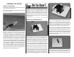
AMA Number Phone Number City, State, Zip Address Name This model belongs to: O.S. GT60 MOUNTING HOLES I.D.
See templates on reverse side.
NOTES: 39