
User Manual

6
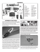
SBD-1 S.Bus Decoder Cables allow the use of existing
analog and digital servos, too. By providing today’s pilots
with tomorrow’s technology, the Futaba S.Bus system is
nothing short of revolutionary.
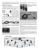
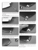
Installing the S.Bus System
Installation is actually simpli ed as compared to your normal
system installation. Using the S.Bus system you plug a battery
into the SBC-1 channel changing tool, using it to program
which channel you want the servo to operate on.
Once programmed, the
servo will operate as
required, regardless of
which lead it is plugged into.
Do this for all of the servos
that you want to operate on
the S.Bus system. Install
the servos in the airplane
and plug them into the S.Bus lead, piggybacking them one
onto another. Once completed, you plug one lead into the
receiver for all of the servos and all of the servos will function
as programmed. One lead operates up to 16 servos!
S.Bus leads are available in a number of different lengths to
accommodate installation into any size airplane, regardless
of its complexity.
There are many choices for the
S. Bus receivers; some are tiny
3-port receivers with others
being up to 18 channels. The 8
PWM outputs can be used as
you would normally set up a
model, allowing you to split the
model and have some of it set up as S.Bus while other servos
are not using the S. Bus system. Something else to note is
that some of the S. Bus servos and receivers are HV, or High
Battery
Servo
Channel
Changing
Tool
Voltage, meaning that you could run a straight 2S LiPo for
your receiver battery.
Many servo choices are
available for use in a wide variety
of aircraft from micros to the
largest models.
Your system is not limited to programming only through the
SBC-1 channel changing tool and your transmitter. Utilizing the
USB interface, the CIU-2, you can do all of the programming
using your PC. Programming with this interface gives more
exibility and programming options than can be achieved
with any other radio system. To utilize standard, non-S.Bus
servos, you simply use the S.Bus decoder instead of the
S.Bus lead.
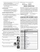
S.Bus System Set-up (using standard servos)
This set-up allows the use of non S.Bus servos. The retract
servo (or controller for electric retracts), optional drop tank
and optional receiver controlled lights are plugged directly
into the receiver.
NOTE: See the included layout drawing for required servos,
servo extension, S.Bus hubs and S.Bus Decoders. This
set-up will also require a SBC-1 S.Bus Channel Setting Tool
(FUTM4190) or CIU-3 USB Interface (FUTM0953) to program
the S.Bus decoders.
Battery
S.Bus Receiver
Hub
Hub
Hub
Servo Servo ServoServo
WING
S.BUS SYSTEM