
User Manual

48
❏
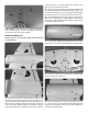
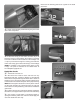
1. Use a box or something similar to prop up the bottom
of the fuselage so the horizontal stabilizer and wing will be
level. Hold a ruler vertically on your workbench against the
widest part (front to back) of the trailing edge of the elevator.
Note the measurement on the ruler.
❏
2. Measure the high rate elevator throw rst. Move the
elevator up with your transmitter and move the ruler forward
so it will remain contacting the trailing edge. The distance
the elevator moves up from center is the “up” elevator throw.
Measure the down elevator throw the same way.
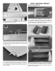
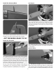
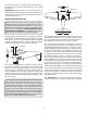
The pushrod farther out
means Less Throw
The pushrod closer in
means More Throw
The pushrod farther out
means More Throw
The pushrod closer in
means Less Throw
At the Servos
At the Control Surfaces
❏
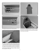
3. If necessary, adjust the location of the pushrod on the
servo arm or on the elevator horn. Once the throws are close,
program the servo end points in the transmitter to ne tune
the throws according to the measurements in the control
throws chart. For the best resolution, adjust the pushrod
locations on the servo arm and elevator horns so that the
servo endpoints are close to 100% on high rates.
❏
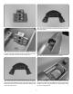
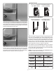
4. Measure and set the low rate elevator throws and the
high and low rate throws for the ailerons, rudder and aps.
If your radio does not have dual rates, we recommend setting
the throws at the high rate settings.
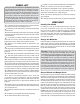
NOTE: The throws are measured at the widest part of the
elevators, rudder, ailerons and aps.
These are the recommended control surface throws:
ELEVATOR
HIGHLOW
5/8" [16mm] 9°3/8" [9mm] 5°
1" [ 25mm] 18°3/4" [19mm] 13°
1-5/8" [ 41mm] 33° down
1-1/4" [32mm] 19°7/8" [22mm] 13°
RUDDER
AILERONS
FLAPS
Down
Up & Down
Up & Down
Right & Left