
User Manual

47
❏
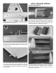
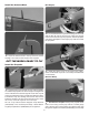
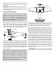
5. Secure the spinner cone to the spinner adapter with a
10-32 x 3/4" [19mm] socket head cap screw (not included).
❏
6. APC Electric Propeller: Enlarge the propeller shaft
hole to 10mm using a metric prop reamer or a letter gauge
size X drill bit. Trim ¼" [6mm] from the end of the spinner
adapter (GPMQ4590) (not included) so that the adapter is
1-1/4" [32mm] long. Install the propeller on the motor shaft
and secure it with the spinner adapter and washer.
❏
7. Secure the spinner cone to the spinner adapter with
a 10-32 x ¾" [19mm] socket head cap screw (not included).
WARNING: NEVER connect the motor battery to the ESC
until you are ready to y. Once the motor battery is connected
the motor could start unexpectedly at any time causing
serious injury.
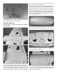
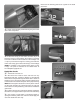
Balance the Model Laterally
❏
1. With the wing level, have an assistant help you lift the
model by the engine propeller shaft and the bottom of the
fuse under the TE of the n. Do this several times.
❏
2. If one wing always drops when you lift the model,
it means that side is heavy. Balance the airplane by
adding weight to the other wing tip. An airplane that
has been laterally balanced will track better in loops
and other maneuvers.
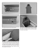
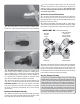
Check the Control Directions
❏
1. Switch on the transmitter and receiver and center the
trims. If necessary, remove the servo arms from the servos
and reposition them so they are centered. Reinstall the screws
that hold on the servo arms.
❏
2. With the transmitter and receiver still on, check all the
control surfaces to see if they are centered. If necessary, adjust
the clevises on the pushrods to center the control surfaces.
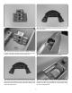
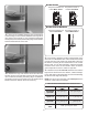
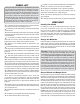
FULL
THROTTLE
RUDDER
MOVES
RIGHT
ELEVATOR
MOVES DOWN
RIGHT AILERON
MOVES UP
LEFT AILERON
MOVES DOWN
RADIO SET UP (STANDARD MODE 2)
❏
3. Make certain that the control surfaces and the carburetor
respond in the correct direction as shown in the diagram.
If any of the controls respond in the wrong direction, use
the servo reversing in the transmitter to reverse the servos
connected to those controls. Be certain the control surfaces
have remained centered. Adjust if necessary.
Set the Control Throws
To ensure a successful rst ight, set up your Giant F6F
Hellcat ARF according to the control throws speci ed in this
manual. The throws have been determined through actual
ight testing and accurate record-keeping, allowing the
model to perform in the manner in which it was intended.
If, after you have become accustomed to the way the Giant
F6F Hellcat ARF ies, you would like to change the throws
to suit your taste, that is ne. However, too much control
throw could make the model too responsive and dif cult
to control, so remember, “more is not always better.”