
User Manual

39
❏
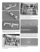
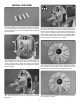
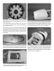
16. Make three 1/2" [13mm] holes in the front of the
dummy engine for removing and installing the 6-32 socket
head cap screws.
❏
17. Sand the inside of the cowl where the cowl ring contacts
the cowl. Then, clean the area with a paper towel dampened
with denatured alcohol.
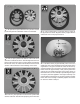
❏
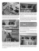
18. Mix 1/2oz [14.7cc] of 30-minute epoxy. Apply the
epoxy to the inside of the cowl where it contacts the cowl
ring. Slide the cowl over the cowl ring, centering it over the
drive washer on the engine and aligning it correctly on the
fuselage. Use masking tape to hold it in position until the
epoxy cures.
❏
19. Unbolt and remove the cowl. Use epoxy to make a llet
between the cowl and the front edge of the plywood cowl
ring. For a stronger llet, mix milled berglass with the epoxy.
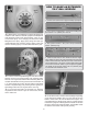
❏
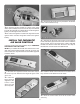
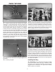
20. Tape a piece of paper over the engine and muf er and
draw the outline of the engine and muf er. Reinstall the cowl
and transfer the outline to the bottom of the cowl.
❏
21. Remove the cowl from the fuselage before cutting
to prevent the berglass dust from entering the carburetor.
Use a high speed rotary tool with a sanding drum to cut the
opening. Start with an undersized hole and slowly enlarge
the opening while test- tting the cowl on the fuselage.
❏
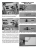
22. Make a 5/16" [8mm] hole in the cowl in front of the cowl
ring for the vent fuel line. Also route the ll fuel line through
the hole in the side of the cowl ring. Insert the aluminum
fuel plug in the ll line. Reinstall the cowl. Apply a drop of
threadlocker on the threads of the 6-32 x ¾" socket head
cap screws before installing them.