
User Manual

37
❏
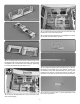
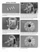
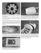
7. We painted the space between the cylinders and the
plywood engine frame at black. Paint is not included.
❏
8. Drill 1/8" [3mm] holes in the bottom of the rocker arms
and in the crankcase as shown. Glue the eighteen aluminum
tubes in the holes. If the dummy engine will be used with the
RimFire 65 motor, the tubes must be ush with the inside
surface of the crankcase to avoid rubbing on the motor.
❏
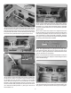
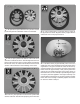
9. Drill 1/16" [1.5mm] holes in the front of the cylinder head
and the crankcase. Glue the red spark plug wire in the holes.
❏
10. Use 6-minute epoxy to glue the dummy engine to
the plywood wood frame. Align the dummy engine with the
embossed circle on the plywood frame.
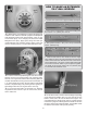
❏
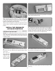
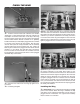
11. Test t the dummy engine assembly in the cowl. Use a
sanding bar with coarse sandpaper to bevel the edges of the
engine frame. The goal is to have the center of the dummy
engine centered in the cowl opening. The back of the engine
frame should be approximately 7-3/8" [187mm] below the
edge of the cowl. Mark the location of the engine frame on
the inside of the cowl. This will help in repositioning the engine
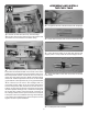
once epoxy has been applied to the engine assembly. Use
masking tape to hold the dummy engine in position and test
t the cowl on the fuselage. Install the propeller and check
for clearance. Refer to Step 15.