
User Manual

34
❏
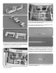
7. Glue the control valve servo tray in the fuselage.
❏
8. Plug the retract control valve servo into the receiver. We
set channel 1 for the retracts for the S.Bus setup.
❏
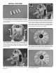
9. Thread the nylon ball socket on the pushrod. Snap the
ball socket onto the ball link ball on the retract control valve.
Install a servo arm 45 degrees from the centerline of the servo.
Mark the pushrod where it crosses the servo arm hole 1/4"
[6mm] from the center of the arm. Make a 90 degree bend
at the mark. Install the pushrod in the servo arm and install
a nylon faslink. Cut the pushrod 1/8" [3 mm] past the faslink.
❏
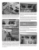
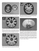
10. Install an air ll valve in the fuselage side in a
convenient location. Refer to the air retracts instructions.
Connect the pressure tank, ll valve and control valve to a
T- tting. Connect the two air lines coming from the tail gear
retract to separate T- ttings. Then, connect the T- ttings to
the control valve. Finally connect the quick connectors to
the T- ttings. Make sure the quick connectors correspond
to the quick connectors installed in the wing. Electrical tape
or tie wraps (not included) can be used to wrap the air lines
together to clean up the installation.
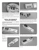
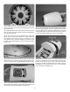
ASSEMBLE AND INSTALL
THE FUEL TANK
❏
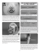
1. Roughen both ends of the brass tubes with sandpaper.
❏
2. Solder fuel line barbs onto one end of the brass tubes.
❏
3. Insert the brass tubes in the fuel tank stopper and
stopper plates. Loosely install the fuel tank stopper screw.
❏
4. Solder the barbs on the other end of the two shorter
brass tubes.
❏
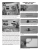
5. Carefully bend the vent line.