
User Manual

33
❏
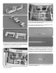
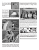
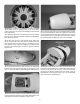
25. Place the ignition module on a piece of R/C foam
rubber (not included) and secure it to the top of the rewall
box with the included four rubber bands. Route the ignition
battery wire through the hole in the box.
❏
26. Connect the ignition module to the engine and to the
ignition switch. Connect the ignition switch to the ignition
battery.
INSTALL THE PNEUMATIC
AIR VALVE CONTROLS
If electric retracts have been installed, skip to ASSEMBLE
AND INSTALL THE FUEL TANK.
NOTE: If you installed the throttle and choke servos on the
right side of the fuselage instead of the left as shown, the
control valve servo tray will need to be assembled opposite
of what is shown.
❏
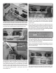
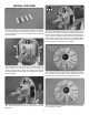
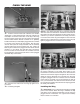
1. Glue the 3mm plywood control valve servo tray to
the servo tray side. Note that the larger tab goes at the
servo end.
❏
2. Glue the
three plywood
supports to the
control valve
servo tray and
servo tray side.
❏
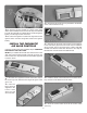
3. Glue the two plywood servo tray doublers to the bottom
of the control valve servo tray.
❏
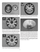
4. Glue the two plywood control valve mount supports
to the sides of the plywood control valve mount. Install the
retract control valve in plywood mount. Install a .080 ball
link ball and .080 nut on the valve. Be sure to use a drop of
threadlocker on the threads of the ball link ball.
❏
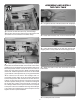
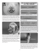
5. Install the retract control valve servo in the retract servo
tray. Use thin CA to harden the screw holes.
❏
6. Glue the control valve mount to the control valve
servo tray.