
User Manual

32
❏
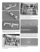
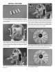
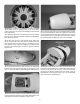
18. Insert the inner pushrod and ball link socket into the
throttle outer pushrod tube. Insert the throttle outer pushrod
tube through the top hole in the plywood pushrod support.
Snap the ball link socket onto the throttle pivot ball. Insert
the choke outer pushrod tube through the bottom hole.
❏
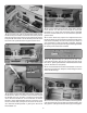
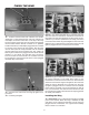
19. Switch on the transmitter, then receiver. Position the
throttle stick so that it is centered on the transmitter. Adjust
the throttle servo arm so that it is centered on the throttle
servo. Move the throttle arm on the carburetor so that the
throttle is open approximately half way. Insert the nylon
clevis in the hole 5/8" [16mm] from the center of the servo
arm. Mark the throttle pushrod ¼" [6mm] from the end of
the threaded rod.
❏
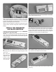
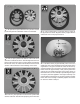
20. Trim the throttle pushrod at the mark, slide a silicone
clevis retainer over the clevis and thread the clevis and
threaded rod ¼" [6mm] into the throttle pushrod. Reinstall
the clevis on the throttle servo arm and check the operation
of the throttle.
❏
21. Now it should only require minor adjustments to the
throttle endpoints on the transmitter so that the throttle opens
and closes completely. Be sure to also set up a switch on
your transmitter to close the throttle completely, stopping
the engine. The plywood pushrod support will be glued after
the choke pushrod has been installed.
❏
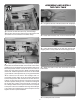
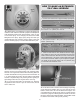
22. Trim approximately 1/8" [3mm] from the end of the
nylon ball link socket. Also trim 3/8" [9mm] from the end of
the 2-56 x 1" [25mm] threaded rod. Thread the ball link socket
onto the threaded rod completely.
❏
23. Thread the ball link socket and threaded rod into the
white inner pushrod tube. Setup the choke linkage the same
as the throttle linkage.
❏
24. Once the choke pushrod is installed, Glue the plywood
outer pushrod support to the side of the ignition battery tray.
Also glue the outer pushrod tubes to the plywood support.