
User Manual

30
❏
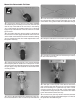
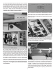
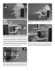
7. Drill a 3/16" [4.5mm] hole at the marks on the rewall
for the throttle and choke outer pushrod tubes. Remove the
engine before drilling the holes. From the 24" [610mm] outer
pushrod tube, cut a 4-1/4" [108mm] and a 7-1/2" [190mm] long
piece. Use medium sandpaper to roughen the outer pushrod
tubes. Clean the tubes with denatured alcohol. Insert the
4-1/4" [108mm] tube in the hole for the choke pushrod and
the 7-1/2" [190mm] tube in the hole for the throttle pushrod
so that they are ush with the front of the rewall. Use thin
CA to glue the tubes to the rewall. Also drill a 5/16" [8mm]
hole at the location for the fuel line. Once the holes are drilled,
install the muf er on the engine and reinstall the engine on the
standoffs. Apply a drop of threadlocker to all the mounting
bolts as they are installed.
❏
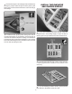
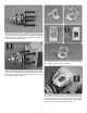
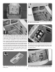
8. Use 6-minute epoxy to glue the sides to the ignition
battery tray.
❏
9. Glue the ignition battery tray in the fuselage. Note that
the wider slot is to the back.
❏
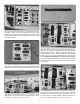
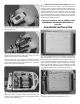
10. Wrap the ignition battery in foam and secure it to the
ignition tray with a hook and loop strap assembled from the
remaining hook and loop material used for the receiver and
receiver battery straps. Note: The battery hatch has been
removed for clarity.
❏
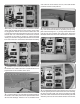
11. Install the ignition switch and optional charge receptical
in the side of the fuselage or in the position of your choice.