
User Manual

28
❏
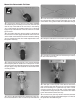
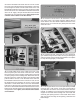
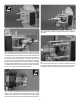
8. Use a sharp hobby knife to open the slot in the bottom
of the rewall box.
❏
9. Solder the bullet and battery connectors on the ESC.
Attach the ESC to the ESC mount with four #4 x ½" [13mm]
sheet metal screws and #4 at washers.
❏
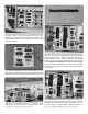
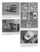
10. Connect a 6" to 8" [152mm to 203mm] long servo
extension to the ESC. Plug the ESC into your receiver. If using
S.Bus with non S.Bus servos plug the ESC into a decoder.
We put the throttle on channel 13.
❏
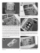
11. Make two battery straps from the second strip of hook
and loop material. Insert the straps in the battery tray. The
location of the batteries forward or aft will be determined
when the plane is balanced.
❏
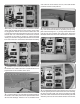
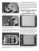
12. WITHOUT THE PROPELLER INSTALLED, check
the rotation of the motor. Switch on the transmitter, then
receiver. Connect the Great Planes Series Connector to
both batteries and plug the Series Connector into the ESC.
Advance the throttle and check that the motor is rotating
counterclockwise. If it is not, switch two of the three bullet
connectors between the motor and ESC. We recommend
that an arming plug be installed. The Schumacher Products
ArmSafe arming kit works great.
If electric powered, skip to INSTALL THE
PNEUMATIC AIR VALVE CONTROLS on
page 33.
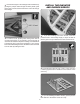
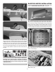
GAS ENGINE INSTALLATION
❏
1. The rewall has two sets of engine mounting bolt
patterns embossed on it. The “+” are for the DLE-55 Rear
Exhaust and DLE-61 Side Exhaust gas engines and the “X”
are for the DLE-55 Side Exhaust gas engines. In the back
of this manual we provide a paper template for mounting
the O.S. GT 60 gas engine. If you are installing an engine
with a different mounting bolt pattern, the rewall also has
crosshairs embossed on it to help center the engine.
❏
2. Drill a 13/64" [5mm] hole through the rewall at each of
the appropriate locations marked with an “X” or “+”.