
User Manual

25
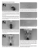
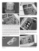
remove the threaded metal clevis and nut from the control
horn end, remove the pushrod from the fuselage, cut it to the
correct length and solder a metal solder clevis on the end.
Reinstall the pushrod from the front and connect the solder
clevis to the servo arms. Reinstall the threaded metal clevis
and 4-40 nut. Apply a drop of thread locker to the threads
and tighten the nut against the clevis. Don’t forget to use
a silicone clevis retainer on all the clevises.
❏
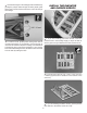
14. Install solder clevis on the rudder servo arm in the
hole 5/8" [16mm] from the center of the servo arm. Thread
the nylon torque rod horn onto the rudder torque rod so that
it is 5/16" [8mm] from the fuselage side. Attach the clevis to
the torque rod horn, center the rudder, and mark the rudder
pushrod where it is to be cut for the solder clevis. Remove
the threaded metal clevis from the control horn end, remove
the pushrod from the fuselage, cut it to the correct length
and solder a metal solder clevis on the end. Reinstall the
pushrod from the front and connect the solder clevis to the
servo arms. Reinstall the threaded metal clevis and 4-40 nut.
Apply a drop of thread locker to the threads and tighten the
nut against the clevis. Again, use a silicone clevis retainer
on the clevises.
❏
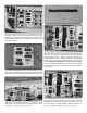
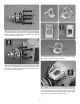
15. Thread a 4-40 nut and a 4-40 metal clevis, 12 turns,
onto each of the 4-40 rigging couplers. Slide a silicone
clevis retainer over each clevis. Install the clevises on the
steering servo arm in the hole 5/8" [16mm] from the center
of the servo arm.
❏
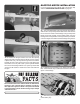
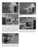
16. Lower the tail gear. Center the servo arm and the tail
gear. Install a swage on each cable, securing it following the
same procedure used on the tail gear ball links. Use a pliers
to crimp the swage tightly on the cable.
❏
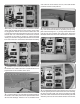
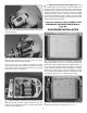
17. The tail gear retract cover can be permanently installed
using CA glue or with screws. If CA glue is used it will be
very dif cult to remove the cover and access the retracts if
needed. To install the cover with screws, tape three pieces
of paper on each side of the fuselage. Put one at each end
of the tail gear opening and one in the middle. Place marks
3/32" [2mm] from the edge of the opening, centered in the
balsa stringer.