
User Manual

24
❏
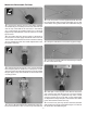
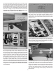
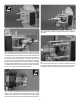
9. Follow your radio setup diagram to connect the elevator,
rudder and tail wheel steering to the receiver. Using S.Bus,
we plugged both elevator servos and the rudder servo into
one decoder and the tail wheel steering servo into a second
decoder. Set one of the elevators on channel 9, the other
on channel 10, the rudder on channel 11 and the tail wheel
steering on channel 12. Plug both decoders into the terminal
box. Secure the servo connections with heat shrink tubing.
❏
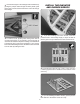
10. Switch on your transmitter and then the receiver. Center
the elevator trims. Install a servo arm on both elevator servos
perpendicular to the centerline of the servo.
❏
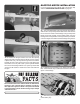
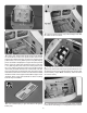
11. Insert the three 4-40 x 36" [915mm] metal pushrods in
the elevator and rudder pushrod outer pushrod tubes at the
aft end of the fuselage. Thread a 4-40 nut, threaded clevis
and a silicone clevis retainer, 16 turns, onto both elevator
pushrods and the rudder pushrod.
❏
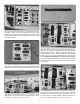
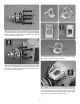
12. Mount the control horns to the elevators the same way
they were mounted on the ailerons, by drilling 3/32" [2.5mm]
pilot holes and using #4 x ½" [13mm] sheet metal screws.
Use thin CA glue to harden the screw holes. Attach the
threaded clevis in the outer hole of the elevator control horn.
❏
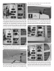
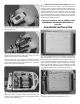
13. Install solder clevises on the elevator servo arms in the
hole 3/8" [9.5mm] from the center of the servo arm. Following
the same procedure that was done for the aileron and ap
pushrods, center the elevator and mark the elevator pushrods
where they are to be cut for the solder clevises. One at a time,