
User Manual

14
❏
❏
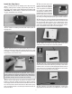
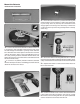
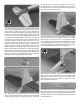
3. Install the metal solder clevis in the 2nd hole from
the outer end of the control horn. Center the aileron servo
and aileron. Mark the pushrod where it meets the solder
clevis. Remove the pushrod and the solder clevis and cut
the pushrod 1/4" [6.5mm] past the mark. Solder the solder
clevis to the pushrod using the techniques described in the
following Hot Tip.
Hot Tip
HOW TO SOLDER
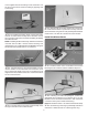
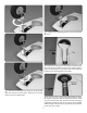
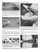
1. Use denatured alcohol or other solvent to thoroughly
clean the pushrod. Roughen the end of the pushrod with
coarse sandpaper where it is to be soldered.
2. Apply a few drops of soldering ux to the end of the
pushrod. Then, use a soldering iron or a torch to heat it.
“Tin” the heated area with silver solder by applying the
solder to the end. The heat of the pushrod should melt the
solder – not the ame of the torch or soldering iron – thus
allowing the solder to ow. The end of the wire should be
coated with solder all the way around.
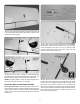
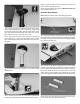
3. Place the clevis on the end of the pushrod. Add an-
other drop of ux. Then, heat and add solder. The same
as before, the heat of the parts being soldered should
melt the solder, thus allowing it to ow. Allow the joint to
cool naturally without disturbing. Avoid excess blobs, but
make certain the joint is thoroughly soldered. The solder
should be shiny, not rough. If necessary, reheat the joint
and allow to cool.
4. Immediately after the solder has solidi ed, but while it
is still hot, use a cloth to quickly wipe off the ux before
it hardens. Important: After the joint cools, coat the joint
with oil to prevent rust. Note: Do not use the acid ux that
comes with silver solder for electrical soldering.
This is what a properly soldered clevis looks like – shiny
solder with good ow, no blobs and ux removed.
❏
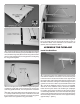
4. Slide a silicone clevis retainer over the solder clevis.
Reinstall the aileron pushrod with the threaded clevis attached
to the control horn. Adjust the threaded clevis so that the
aileron is centered. Apply a drop of thread locker to the
threads of the pushrod behind the clevis. Tighten the 4-40
nut against the clevis.
❏
5. Assemble and connect the ap pushrods following
the same procedure. We installed the pushrod in the outer
hole of the control horn and the hole 5/8" [16mm] from the
center of the servo arm.
❏
6. Return to step 1 and install the aileron and ap pushrods
on the right wing.
The F6F Hellcat was tted with the 2,100 hp Pratt &
Whitney R-2800-10W engine, the same engine used in
the Corsair and the P-47 Thunderbolt. It had a gross
weight of 15,413 lbs. Its maximum speed was 376 mph
at 23,400 ft. It carried six 50-caliber machine guns with
400 rounds of ammunition.