
User Manual

13
❏
❏
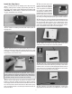
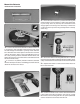
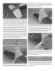
4. Secure the aileron hatch to the wing using four #2
x 3/8" [9.5mm] at head sheet metal screws. Use thin CA to
harden the screw threads.
❏
❏
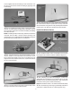
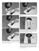
5. Go back to step 1 on page 11 and install the right
ap and aileron servos following the same procedure. The
left and right wing ap servos face the same direction.
NOTE: If installing S.Bus, we put the right wing ap #2 on
channel 8 and right aileron #2 on channel 6.
Install the Aileron and Flap Pushrods
Do the left aileron rst. Temporarily plug the aileron servo
into the receiver. Switch on the transmitter and plug a receiver
battery into the receiver. Center the aileron trim and adjust the
aileron servo arm so that it is perpendicular to the centerline
of the servo.
❏
❏
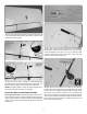
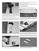
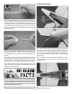
1. Slide a silicone clevis retainer over a 4-40 threaded
metal clevis. Thread a 4-40 nut followed by the 4-40 metal
clevis, threaded 16 turns onto a 4-40 x 6" [152mm] metal
pushrod. Attach the clevis to the aileron servo arm 5/8"
[16mm] from the center of the arm.
❏
❏
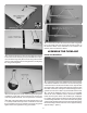
2. Position the control horn so that it is in line with the
pushrod and over the plywood mounting plate. The holes
in the control horn should be aligned with the hinge line of
the aileron. On the aileron, mark the four mounting holes.
Remove the control horn and drill a 5/64" [2mm] pilot hole at
each mark. Do not drill completely through the aileron. Attach
the control horn using four #4 x ½" sheet metal screws. Use
thin CA to harden the holes.