
User Manual

12
of the supplied heat shrink tubing in half and slide it over
the servo connections. Shrink the tubing by applying heat
to the tubing.
❏
❏
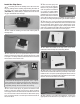
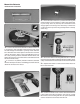
10. If installing the S.Bus setup, connect the S.Bus
decoder or S.Bus hub to the ap servo extension. Secure
the connection with a piece of heat shrink tubing if installing
the S.Bus decoder.
NOTE: If installing the Non S.Bus setup, follow the instructions
included with the SBC-1 S.Bus Channel Setting Tool
(FUTM4190) or CIU-3 USB Interface (FUTM0953) to program
the decoder. We set ap number 1 to channel 7.
❏
❏
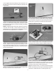
11. Plug the ap servo and receiver battery into the
receiver. Switch on the transmitter and center the servo
trims. Temporarily install a servo arm on the ap servo, 60
degrees from the centerline of the servo. Test the movement
for the correct direction.
❏
❏
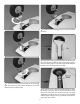
12. Use the string in the wing to pull the ap wires
through to the aileron servo hatch location.
❏
❏
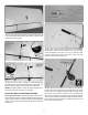
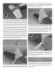
13. Place the ap servo hatch with the servo in the wing.
Be certain that the hatch is positioned correctly as shown.
Secure the hatch using four #2 x 3/8" [9.5mm] at head sheet
metal screws. Use thin CA to harden the screw threads.
Install the Aileron Servo
❏
❏
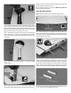
1. Install the aileron servo on the aileron servo hatch
following the same method used to install the ap servo.
❏
❏
2. Following your radio setup diagram, connect the
appropriate servo extension to your aileron servo. Or, plug
the aileron servo into the S.Bus decoder or hub. Secure the
connectors with a piece of heat shrink tubing.
Note: We set aileron number 1 to channel 5 in the S.Bus setup.
❏
❏
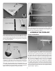
3. Use the string in the wing to pull the ap and aileron
extensions or S.Bus decoder or hub through the wing.