Tower Speaker with color changing lights Read this material before using this product. Failure to do so can result in serious injury. SAVE THIS MANUAL.
Important Safety Instructions CAUTION: TO REDUCE THE RISK OF ELECTRIC SHOCK, DO NOT REMOVE COVER (OR BACK). NO USER-SERVICEABLE PARTS INSIDE. REFER SERVICING TO QUALIFIED SERVICE PERSONNEL FCC NOTICE This equipment has been tested and found to comply with the limits for a Class B digital device, pursuant to part 15 of the FCC Rules. These limits are designed to provide residential protection against harmful interference in a residential installation.
13. Unplug this apparatus during lightning storms or when unused for long periods of time. 14. Refer all servicing to qualified service personnel. Servicing is required when the apparatus has been damaged in any way, such as power-supply cord or plug is damaged, liquid has been spilled or objects have fallen into the apparatus, the apparatus has been exposed to rain or mositure does not operate normally, or has been dropped. 15.
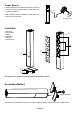
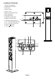
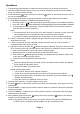
Power Source Insert the small plug from the supplied AC/DC Adaptor to the DC IN Jack on the unit. Insert the AC/DC adaptor to a wall outlet having AC 100-240V~, 50/60 Hz. TO DC IN JACK NOTE: This AC/DC Adaptor is intended to be correctly orientated in a vertical or floor mount position. To Wall Outlet Installation 1. Main Body 2. Wooden Base 3. Screws 4. Speaker Net 5. Speakers 6. Remote Sensor 6 5 1 4 2 3 The speaker net can take out and reassemble as the figures above.
Location of Controls 1. FM ANT (FM ANTENNA) 2. POWER ON/OFF SWITCH 3. DC IN JACK 4. AUX IN 2 JACKS 5. AUX IN 1 JACK 6. (BLUE TOOTH) INDICATOR 7. AUX 1 INDICATOR 1 8. AUX 2 INDICATOR 9. STANDBY/FM INDICATOR 10. MODE / LIGHTT BUTTON 11. STANDBY ON/OFF BUTTON 12. VOL - (VOLUME DOWN) BUTTON 4 2 13. VOL + (VOLUME UP) BUTTON 14. TUNE +/ BUTTON 15.
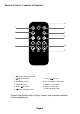
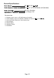
Remote Control - Location of Controls 11 LED ON/OFF 1 2 3 4 6 5 7 8 10 9 1. Standby ON/OFF BUTTON 2. (MUTE) BUTTON 7. TUNE +/ BUTTON 3. SOURCE BUTTON 8. VOL (VOLUME) +/- BUTTONS 4. RESET BUTTON 9. TREBLE +/- BUTTONS 5. TUNE -/ 10. BASS +/- BUTTONS 6. BUTTON 11.
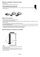
Batteries Installation ( Remote Control ) -First time use: Remove and discard the insulation film as the figure on right. -Replacing battery for the remote control: 1. Push and slide out the battery tray as the figure below. 2. Replace the battery by a new button cell with the polarity ”+” face up as the figure below and the rear of remote control. 3. Close the battery up Batterie Precautions: Follow these precautions when using a battery in this device: 1.
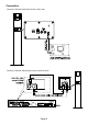
Connection Connect to External Audio Device with 3.
Operations 1. Connected the external Audio or Video/Audio Devices to the unit as previous procedures. 2. Slide the POWER ON/OFF Switch on the rear of unit to ON position to turn the unit to Standby mode. The Power Indicator will light. 3. Press and hold the button on the unit or press the button on the Remote Control to turn on the unit from Standby mode. 4. Press the SOURCE button on the unit or Remote Control to select input source as desire. A.
General Specifications DC DC 12V,2A 3V,1 x CR 2025 button cell (Included) FM 87.5-108 MHz 4 x 4 Ohms, 6 W Accessories: 1 x Remote Control ( uses 1 x CR 2025 button cell,induded ) 1 x AC/DC Adaptor ( Input: AC 100-240V~,50/60Hz 1A; Output DC 1 x Audio Connection Cable with 3.