
Owner manual
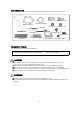


【INSTALLATION PROCEDURE】
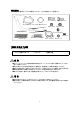
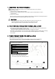
1. Usin
g
the ima
g
e below as a reference, remove the stud bolt on the turbine usin
g
the two included hex nuts.
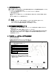
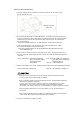
2. Insert Down
p
i
p
e B throu
g
h the Clam
p
Band (Part ⑦) and then insert into Down
p
i
p
e A
Test fit the assembly to the turbine with the included
g
asket. Use the su
pp
lied Ca
p
Bolt
and Disc S
p
rin
g
in
p
lace of the removed stud and reuse the stock nuts and bolts for
the remainin
g
fixin
g
s.
※Use the su
pp
lied
g
asket (Part ①), Ca
p
Bolt (Part ③), Disc S
p
rin
g
(Part ④)
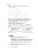
3. Usin
g
the su
pp
lied bolts, nuts and
g
askets, test fit the assembly to the muffler.
Then, test fit the bracket usin
g
the stock bolts.
※Use the su
pp
lied
g
asket (Part ②), Flan
g
e Bolt (Part ⑤) Flan
g
e Nut (Part ⑥),
Clam
p
Band (Part ⑦)
4. Ensure there is sufficient clearance from other
p
arts. Then, workin
g
from the front to
the rear, com
p
letely ti
g
hten down the bolts in order. The clam
p
band should be ti
g
htened
down last.
Tor
q
ue s
p
ecifications Ca
p
Bolts, Flan
g
e Nuts (Part ③,⑥) [34~39Nm (3.5~4.0k
g
f-m)]
Stock Turbo Bolts & Nuts
[
34~39N・m
(
3.5~4.0k
g
f-m
)]
Remove using the
'double nut'
Stock
Turbo
Bolts
&
Nuts
[34 39N m(3
.
54
.
0kgf m)]
Stock Bracket Bolt [36N・m(3.7k
g
f-m)]
Clam
p
Band (Part ⑦) [25N·m(2.6k
g
f-m)]
5. When not attachin
g
an A/F meter, install the co
pp
er washer (Part ⑨) and blind
p
lu
g
(Part ⑧)
Tor
q
ue s
p
ecifications Blind Plu
g
(Part ⑧) [40~50N·m(4.1~5.0k
g
f-m)]
CAUTION
・De
p
endin
g
on the vehicle, the o2 sensor and heat shield may become too close.
In such a case,
p
lease ad
j
ust/modify accordin
g
ly.
・Ensure sufficient clearance and correct fitment has been achieved before ti
g
htenin
g
down the nuts and bolts com
p
letel
y
.
In some cases, there may be insufficient clearance due to differences in vehicle
s
p
ecification. In such a case, loosen the bolts of each com
p
onent and ad
j
ust
the
p
roduct until sufficient clearance is achieved before re-ti
g
htenin
g
down all the bolts.
・Usin
g
the
p
roduct whilst there is oil or other debris on it can cause blemishes or
burn marks.
・Ensure that a
pp
ro
p
riate thermal insulation is installed for the
p
arts and intended use
of the vehicle. Ensure all
p
arts are de
g
reased after installation.
5. Reconnect the battery's ne
g
ative terminal.
8