
User Manual
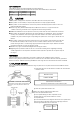

5. ASSEMBLY VERIFICATION
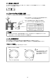
① Check the clearance Piston's skirt and crankweight in relation to each other during rotation.
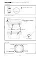
② Confirm that the Piston does not protrude more than required from the cylinder bore at Top Dead Center.
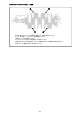
③ Be sure to calculate the final compression ratio once done.
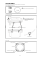
V
1 1 Cylinder Displacement (cc)
V
2 Combustion Chamber Volume (cc)
V
3 Gasket Capacity (cc)
V
4 Crown Capacity (cc)
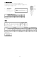
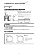
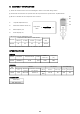
COMPRESSION RATIO REFERENCE CHART
The above compression ratio is based on the combustion chamber volume of 50cc
SPECIFICATIONS
PISTON
Compression Ratio Reference (With Gasket)
Diameter
Gasket Bore
Size
t=0.7mm t=1.0mm t=1.2mm t=1.5mm
Φ99.75 8.5 8.3 8.2 8.0 Φ101.0
Compression
Ratio
V
1
V
2+
V
3
+
V
4
+1
V
2
V
3
V
1
V
4
=
11
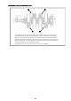
PISTON
CONROD
CRANKSHAFT
Diameter Part Number Compression Height Pin Dia.
Crown Displacement
Volume (cc)
(cc)
φ99.75 1182997312 30.70 φ23 19.50 2593
φ52 16.5
Part
Number
Conrod Conrod Bolt Conrod Bearing
Center Distance
Big End Dia. Small End Dia. x Thickness
Material Screw Size Neck Length Inner Dia. Bearing Width
(mm)
x Thickness (Inner Bush Dia.)
Stroke (mm)
83.0 (STD: 79.0)
125012 127.8 φ55×21.4 φ23×21.4
SNCM
4340
3/8-24 40
11