
Manual
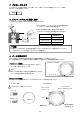

5. ASSEMBLY VERIFICATION
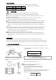
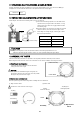
① Check the clearance Piston's skirt and crankweight in relation to each other during rotation.
② Confirm that the Piston does not protrude more than required from the cylinder bore at Top Dead Center.
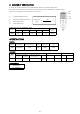
③ Be sure to calculate the final compression ratio once done.
V
1 1 Cylinder Displacement (cc)
V
2 Combustion Chamber Volume (cc)
V
3 Gasket Capacity (cc)
V
4 Crown Capacity (cc)
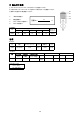
COMPRESSION RATIO REFERENCE CHART
SPECIFICATIONS
PISTON
CONROD
Displacement
(cc)
2123
Diameter
Compression Ratio Reference (With Gasket)
Gasket Bore
Size
t=0.7mm t=1.0mm t=1.2mm t=1.5mm t=1.8mm
Φ92.5 8.2 8.0 7.9 7.7 7.6 Φ93.5
Diameter Part Number Compression Height Pin Dia.
Crown
Volume (cc)
φ92.5 1181 925312 31.00 φ23 18.43
Part
CDi
Conrod Conrod Bolt Conrod Bearing
Compression
Ratio
V1
V2+V3+V4
+1
V2
V3
V1
V4
=
7
CRANKSHAFT
Stroke (mm)
79 (STD:75.0)
125008 130.5 φ55×21.4 φ23×21.4
Part
Number
Center Distance
Big End Dia.
(mm)
x Thickness (Inner Bush Dia.)
Material
SNCM
4340
Screw Size
3/8-24
Neck Length Inner Dia. Bearing Width
40 φ52 16.5
Small End Dia. x Thickness
7