
Information Sheet


1-203-857-2200 • www.wejit.com
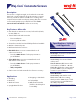
Wej-Con
®
Concrete Screws
Page 2 of 4
Installation Information
dh = Attachment
Thickness
hnom = Embedment
(min. of 1", max. of
1-3/4")
dh+hnom = Wej-Con Anchor
Length
hnom + x = Hole Depth
dh
hnom
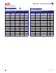
Ultimate and Allowable Loads (lbs.) –Normal-Weight Concrete
Anchor
Dia.
(in.)
Drill
Bit Dia.
(in.)
Embed.
Depth
(in.)
Allowable Ultimate
2,000 psi 3,000 psi 4,000 psi 2,000 psi 3,000 psi 4,000 psi
Tension Shear Tension Shear Tension Shear Tension Shear Tension Shear Tension Shear
3/16 5/32
1 125 175 130 175 135 180 500 700 520 700 540 720
1-1/4 135 210 150 215 175 230 540 840 600 860 700 920
1-3/8 175 225 190 225 210 230 700 900 760 900 840 920
1-1/2 180 230 220 230 245 235 720 920 880 920 980 940
1-3/4 250 235 275 235 300 240 1000 940 110 0 940 1200 960
1/4 3/16
1 155 215 160 220 220 230 620 860 640 880 880 920
1-1/4 205 285 265 310 335 355 820 1140 1060 1240 1340 1420
1-3/8 230 325 300 340 365 360 920 1300 1200 1360 1460 1440
1-1/2 255 350 330 355 400 360 1020 1400 1320 1420 1600 1440
1-3/4 400 370 420 375 440 375 1600 1480 1680 1500 1720 1500
Instructions
1. Use the correct size masonry drill bit (one included in
every box) and drill the hole at least
1/4" deeper than the calculated embedment depth.
It is recommended that a minimum of 1" and a
maximum of 1-3/4" embedment be used.
2. Clean the hoe using a nylon brush and
compressed air.
3. Place the anchor point through the xture into hole.
4. Drive the anchor in a single continues motion until
the anchor is set rmly against the xture.
NOTE: Always wear safety glasses. Normal safety precautions should be
observed when drilling the holes to avoid electrical installations, other utilities
and reinforcement bars.
2
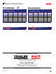
Ultimate and Allowable Loads (lbs.) – Hollow Block
Anchor Dia.
(in.)
Drill Bit
Dia. (in.)
Embed.
Depth (in.)
Allowable Ultimate
Tension Shear Tension Shear
3/16 5/32
1 115 165 460 660
1-1/4 125 200 500 800
1-3/8 150 205 600 820
1-1/2 155 215 620 860
1-3/4 160 220 640 880
1/4 3/16
1 135 190 540 760
1-1/4 185 275 740 1100
1-3/8 220 320 880 1280
1-1/2 245 345 980 1380
1-3/4 290 365 116 0 1460
1 3
4
*Allowable load capacities are calculated using an applied safety factor of 4:1
*Allowable load capacities are calculated using an applied safety factor of 4:1
Performance Data