
User's Manual

7
3. Electrical Connection. All electrical connections required for this unit must be performed by a certied
electrician. Built-in models are equipped with a 3/4” (19mm) diameter x 4ft. (122cm) long exible conduit
containing power lead pigtails and a ground wire. It is necessary that this conduit and the wiring leads
connect at a junction box in accordance with local codes. Be sure to check the data plate on the front of
the unit to be sure the power supply is correct. 115V units operate on voltage ranging from 110V to 125V.
220V units operate on voltage ranging from 208V to 240V.
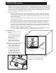
4. Mount Unit in Cabinet.
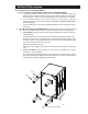
a. Remove the drawer(s) from the unit, pull the drawer(s) out to the stop. Grasp the entire drawer
assembly at the sides as if to lift it and locate your thumbs on the tabs of the drawer slide (gure
2-7). Press down on these tabs with your thumbs and simultaneously pull out on the drawer. Set
drawer assembly aside.
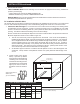
b. Lift
the unit form both sides and start its backside into the cut out. Push back until the trim ange
meets the face of the xture.
c. Place
a level on the oor of the unit and check from side to side and front to back. If adjustments
are necessary, slide the entire unit out of the xture and adjust the leveling feet as required.
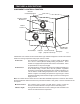
d. Secure
the unit into position after leveling. There are two holes in the unit bottom for this purpose
(See Figure 2-6). Place a drill bit down through these two holes and bore two pilot holes into the
crossbrace beneath. Tighten a pair of at head sheet metal screws down through these holes
and into the crossbrace. The unit is now installed.
e. Replace the drawers. NOTE: The drawers of multiple drawer units are individually identied
(ex: “TOP”, “2” AND “3”). They should be reinstalled in their respective positions.
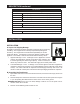
E. Initial Start-up
1. Turn on the branch line circuit
breaker
2. Set the thermostat control dial
at “10” the indiactor light will
come on indicating that unit is
calling for heat.
3. After a few minutes have
elapsed, open a drawer and
check that the unit is heating.
NOTE:
If your unit is equipped with
a separate thermostat for each
drawer, complete Steps 2 & 3
for each drawer individually.
4. If unit fails to heat, recheck to
be sure circuit breakers are
on and electrical connections
are properly made. If it still
fails to heat, call a
Toastmaster
Authorized Service Agent.
INSTALLATION continued
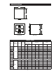
Bolts used as
leveling feet
Bolts used as
leveling feet
Drill starter holes and attach
hot food server to support through
these two holes.
Use flat head screws.
IL2090-02
Drawer
Release Tabs
IL2101
Above: Figure 2-6, Cabinet Mounting
Left: Figure 2-7, Drawer Release Tabs