
Manual
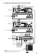


23
[VX-2000DS]
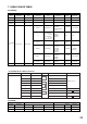
AC IN 3P inlet
–
Supplied cable
–
230 V AC, 50/60 Hz
––
[VX-200PS]
AC IN 3P inlet
–
Supplied cable
–
230 V AC, 50/60 Hz
––
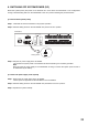
DS-SF LINK RJ45 (female) RJ45 (male) Cat. 5 STP RJ45 (male) VX-2000SF DS-SF LINK RJ45 (female)
BATTERY
POWER IN
Screw terminal
Unprocessed cable
end
6-1/0AWG
Unprocessed cable
end
Lead-acid battery
Electrode
(+, –)
–
PS IN Screw terminal
Round terminal
10 – 14 AWG
Round terminal
VX-200PS PS OUT Screw terminal
PS OUT Screw terminal
Round terminal
10 – 14 AWG
Round terminal
VX-2000DS PS IN Screw terminal
DC POWER
OUT
Screw terminal
Round terminal
–
Round terminal
VX-2000
VX-2000SF
VP-2064/2122/2241
/2421
DC POWER
IN
2P screw terminal
Terminal
Name
Equipment
Receptacle
Plug Cable Type Plug Equipment
Terminal
Name
Equipment
Receptacle
Terminal to Connect Cable Type Equipment to be Connected to
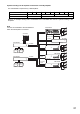
Terminal
Name
Equipment
Receptacle
Plug Cable Type Plug Equipment
Terminal
Name
Equipment
Receptacle
Terminal to Connect Cable Type Equipment to be Connected to
DC plug
(Outer diameter:
F5.5 mm
Inner diameter:
F2.1 mm
Length: 9.5 mm)
RM-200X
RM-200SA
RM-200M
DC IN
DC jack
12 – 24 AWG
Unprocessed cable
end
RM-200XF
LINK
(DC Power
In +/)
9P plug-in screw
terminal
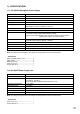
7. CABLE USAGE TABLE
14 – 18 AWG
14 – 18 AWG
Round terminal
SX-2000SM
SX-2100AI
SX-2000AO
SX-2100AO
SX-2000CI
SX-2000CO
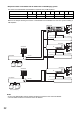
DC POWER
IN
4P removable
terminal plug
Round terminal
VM-3240VA
VM-3360VA
VM-3240E
VM-3360E
DC POWER
IN
2P screw terminal
8 – 10 AWG
12 – 24 AWG
Round terminal
RM-200SF
RM-300MF
DC IN 24 V Screw terminal
Connector Name
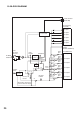
• VX-2000DS' DS-SF LINK Connections
DS-SF Link
RJ45 Pin No.
Orange/white
Shield
Brown
Brown/white
Green
Blue/white
Blue
Green/white
Input/0 – 3.3 V
Input (DC)/3.3 V
Output/0 – 3.3 V
Orange
Connection Check
Chassis GND
Battery Check Activation
NC
3.3 V DC Input
AC Off
DC Off
Charging Circuitry Failure
Battery Failure
Colour Pair Assignment Direction/Level
Shield
1
2
3
4
5
6
7
8