
User Manual
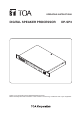
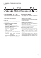
Table Of Contents
- 1. IMPORTANT SAFETY INSTRUCTIONS
- 2. SAFETY PRECAUTIONS
- 3. GENERAL DESCRIPTION
- 4. FEATURES
- 5. HANDLING PRECAUTIONS
- 6. Nomenclature AND FUNCTIONS
- 7. SYSTEM CONFIGURATION EXAMPLE
- 8. MUTE FUNCTION OPERATION
- 9. PRESET NUMBER INDICATION FUNCTION
- 10. CONTROL METHOD USING THE CONTACT INPUT TERMINALS
- 11. FIRMWARE VERSION INDICATION
- 12. INITIALIZING THE DP-SP3
- 13. INSTALLATION
- 14. CONNECTION
- 15. Block DIAGRAM
- 16. SPECIFICATIONS
- 17. DIMENSIONAL DIAGRAM
8
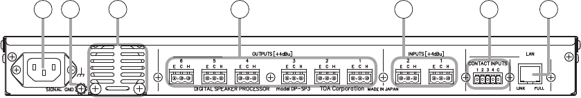
[Rear]
9
11 12 13 14 1510
9. AC power input terminal
Connect this terminal to an AC power source with
the supplied dedicated AC power cord.
10. Functional ground terminal
Hum noise may be generated when external
equipment is connected to the unit. Connecting
this terminal to the functional ground terminal
of the external equipment may reduce the hum
noise.
Note: This ground is not for protective ground.
11. Exhaust vent
Forcibly exhausts the air let in from the front.
12.Outputterminals[OUTPUTS+4dBu,1−6]
+4 dB*, 600 Ω, balanced, removable terminal
block
13.Inputterminals[INPUTS+4dBu,1−2]
+4 dB*, 600 Ω, balanced, removable terminal
block
14. Contact input terminals
[CONTACTINPUTS1−4,C]
Removable terminal block, 4-channel contact
input terminal
*0dB=0.775V
Following controls can be performed using these
terminals.
• Presetmemoryrecall
• MuteON/OFF
• Volumecontrol(UP/DOWN)
For the control method, see p. 14, “CONTROL
METHOD USING THE CONTACT INPUT
TERMINALS.”
Tip
UsethesuppliedDP-SP3PCSoftwaretoassign
control functions to the terminals.
15. LAN p ort
ConnectthisporttotheLAN-connectedswitching
hubwithaLANcable.
• LINKindicator
Lightswhenthelinkisestablishedandduring
data transmission or reception.
• FULLindicator
LightsduringFullduplexoperation.
The DP-SP3’s default IP address is
“192.168.14.1”.
Use the supplied DP-SP3 PC Software to
perform IP address setting.