
User Manual
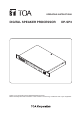
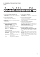
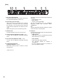
Table Of Contents
- 1. IMPORTANT SAFETY INSTRUCTIONS
- 2. SAFETY PRECAUTIONS
- 3. GENERAL DESCRIPTION
- 4. FEATURES
- 5. HANDLING PRECAUTIONS
- 6. Nomenclature AND FUNCTIONS
- 7. SYSTEM CONFIGURATION EXAMPLE
- 8. MUTE FUNCTION OPERATION
- 9. PRESET NUMBER INDICATION FUNCTION
- 10. CONTROL METHOD USING THE CONTACT INPUT TERMINALS
- 11. FIRMWARE VERSION INDICATION
- 12. INITIALIZING THE DP-SP3
- 13. INSTALLATION
- 14. CONNECTION
- 15. Block DIAGRAM
- 16. SPECIFICATIONS
- 17. DIMENSIONAL DIAGRAM
7
1
23 4 5 6 7 8
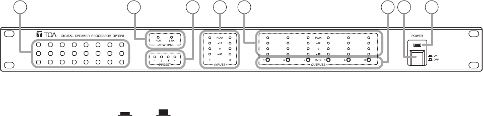
6. NOMENCLATURE AND FUNCTIONS
[Front]
1. Power switch [POWER ON, OFF]
Power is switched on and off with each depression
of this switch.
2. Power indicator [POWER]
Lightswhenthepowerisswitchedon.
3. Intake vent
Letsintheairfromthefrontandforciblyexhausts
it from the rear.
4. Operation status indicators [STATUS]
• RUNindicator[RUN]
IndicatestheDP-SP3'soperationstatus.
Lightsgreen: Normaloperation
Flashesgreen: Muteswitchesinlockmode
Flashesorange:Fanfailure
Flashesred: DSPoperationfailure
Unlit: CPUfailure
• LINKindicator[LINK]
Indicates the connection status with the DP-SP3
PC Software.
Lightsgreen: Preset memory recall being
interlocked.
Flashesgreen: Communicating with PC or
external device.
Unlit: Noconnectionisestablished.
5. Preset indicators [PRESET]
The indicator of the Preset No. currently being
selected lights.
6. Input level indicators [INPUTS]
Indicate the audio input levels.
NotethattheinputlevelistoohighwhenthePEAK
indicator always lights.
7. Output level indicators [OUTPUTS]
Indicate the audio output levels.
Note that the output level is too high when the
PEAKindicatoralwayslights.
Adjust the DP-SP3unit'svolume levelby the PC
with the DP-SP3 PC Software installed.
8. Mute switches [MUTE, 1 through 6]
Pressing the Mute switch causes the corresponding
channel's output to bemutedandthe "−40" level
LED of the Output level indicators (7) ashes
orange.
Pressing it again cancels mute, and the indicator
goes off.
All mute switches can be placed in lock mode
using the supplied DP-SP3 PC software. Pressing
any mute switch in lock mode causes the RUN
indicator(4)toashgreen.