
User Manual
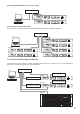
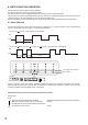
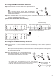
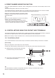
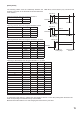
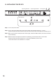
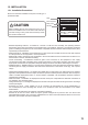
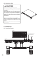
Table Of Contents
- 1. IMPORTANT SAFETY INSTRUCTIONS
- 2. SAFETY PRECAUTIONS
- 3. GENERAL DESCRIPTION
- 4. FEATURES
- 5. HANDLING PRECAUTIONS
- 6. Nomenclature AND FUNCTIONS
- 7. SYSTEM CONFIGURATION EXAMPLE
- 8. MUTE FUNCTION OPERATION
- 9. PRESET NUMBER INDICATION FUNCTION
- 10. CONTROL METHOD USING THE CONTACT INPUT TERMINALS
- 11. FIRMWARE VERSION INDICATION
- 12. INITIALIZING THE DP-SP3
- 13. INSTALLATION
- 14. CONNECTION
- 15. Block DIAGRAM
- 16. SPECIFICATIONS
- 17. DIMENSIONAL DIAGRAM
17
4
A CB
Ver. 2.1.
(Example)
Indicates "A." Indicates "B." Indicates "C."
1
2
3
4
9
5
6
7
8
5
6
7
8
8
5
6
7
8
1
2
3
4
9
9
2 3
4
1
DP-SP3
Indicates "A." Indicates "B."
Indicates "C."
Lights
Lights
Lights
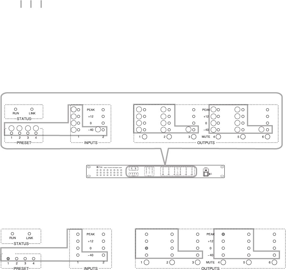
11. FIRMWARE VERSION INDICATION
TheDP-SP3’srmwareversioncanbeconrmedbycheckingthelightingindicatorstatusontheDP-SP3’s
front panel.
• FirmwareVersionIndication
TheDP-SP3’srmwareversionisexpressedasshowninthefollowingexample.
Here,theindividualnumbersaredenotedbyA,B,andC.
• Howtocheckrmwareversion
WhentheDP-SP3isactivated,theindicatorsonthefrontpanellightfor3seconds,indicatingthegureof“A,”
“B,”and“C.”
Thegurethateachindicatorindicatesisasfollows.
Note: Ifalltheindicatorsin“B”and“C”sectionsareunlit,itrepresents“0.”
In the above example of “Ver. 1.2.4”, the indicators of each section light as follows.