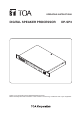
OPERATING INSTRUCTIONS DIGITAL SPEAKER PROCESSOR D IG ITA L SP EA KE R PR OC ES SO R DP -S DP-SP3 P3 RU N STA LIN TU K S 1 2 PR ES 3 PE ET 4 AK +1 2 0 1 – 40 INP UT S 2 1 PE AK +1 2 2 0 3 – 40 M U OU TE 4 TP UT S 5 6 PO WE R ON OFF Thank you for purchasing TOA’s Digital Speaker Processor. Please carefully follow the instructions in this manual to ensure long, trouble-free use of your equipment.
TABLE OF CONTENTS 1. IMPORTANT SAFETY INSTRUCTIONS ............................................ 3 2. SAFETY PRECAUTIONS .............................................................................. 4 3. GENERAL DESCRIPTION ........................................................................... 6 4. FEATURES ............................................................................................................. 6 5. HANDLING PRECAUTIONS ............................................................
1. IMPORTANT SAFETY INSTRUCTIONS • Read these instructions. • Keep these instructions. • Heed all warnings. • Follow all instructions. • Do not use this apparatus near water. • Clean only with dry cloth. • Do not block any ventilation openings. Install in accordance with the manufacture's instructions. • Do not install near any heat sources such as radiators, heat registers, stoves, or other apparatus (including amplifiers) that produce heat.
2. SAFETY PRECAUTIONS • Before installation or use, be sure to carefully read all the instructions in this section for correct and safe operation. • Be sure to follow all the precautionary instructions in this section, which contain important warnings and/or cautions regarding safety. • After reading, keep this manual handy for future reference.
• When moving the unit, be sure to remove its power supply cord from the wall outlet. Moving the unit with the power cord connected to the outlet may cause damage to the power cord, resulting in fire or electric shock. When removing the power cord, be sure to hold its plug to pull. • Do not block the vents on the unit’s front and rear panels. Doing so may cause heat to build up inside the unit and result in fire. Also, periodically clean the ventilation slots of dust.
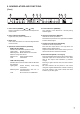
3. GENERAL DESCRIPTION The DP-SP3 is a digital speaker processor equipped with signal processing functions such as Equalizer, Crossover, Matrix, Compressor, and Delay. When connected to a LAN, settings and operations of the DP-SP3 can be performed on a PC with the supplied DP-SP3 PC Software installed. It can be mounted in a 19” EIA component rack (1U size*). *1U size = 44.5 mm (standard size) 4.
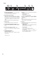
6. Nomenclature AND FUNCTIONS [Front] 3 4 5 6 7 8 1 2 1. Power switch [POWER ON, OFF] Power is switched on and off with each depression of this switch. 5. Preset indicators [PRESET] The indicator of the Preset No. currently being selected lights. 2. Power indicator [POWER] Lights when the power is switched on. 6. Input level indicators [INPUTS] Indicate the audio input levels. Note that the input level is too high when the PEAK indicator always lights. 3.
[Rear] 9 10 11 12 9. AC power input terminal Connect this terminal to an AC power source with the supplied dedicated AC power cord. 10. Functional ground terminal Hum noise may be generated when external equipment is connected to the unit. Connecting this terminal to the functional ground terminal of the external equipment may reduce the hum noise. Note: This ground is not for protective ground. 11. Exhaust vent Forcibly exhausts the air let in from the front. 12.
7. SYSTEM CONFIGURATION EXAMPLE 7.1. Control by the External Control Device The following 2 methods are used to control the DP-SP3 from the external control device. Functions to be controlled differ depending on each method. 7.1.1. Method of direct control This example shows a method to control the DP-SP3 by directly connecting the external device’s contact outputs to the DP-SP3 unit’s contact inputs.
7.2. Control by the M-864D Digital Mixer The M-864D can control up to 4 DP-SP3 units. [Controlling a single DP-SP3] M-864D DP-SP3 DP-SP3: Preset memory recall M-864D: Preset memory number change request Switching hub M-864D DP-SP3 [Controlling multiple DP-SP3 units (up to 3 units)] M-864D DP-SP3 DP-SP3: Preset memory recall M-864D: Preset memory number change request Switching hub M-864D DP-SP3 DP-SP3 7.3. Control by a PC A single PC can control up to 4 DP-SP3 units.
[Controlling multiple DP-SP3 units (up to 4 units)] Switching hub PC DP-SP3 DP-SP3 [Controlling 5 or more DP-SP3 units] It is possible to control DP-SP3 units by activating multiple DP-SP3 PC Software programs. Switching hub PC DP-SP3 DP-SP3 DP-SP3 DP-SP3 DP-SP3 DP-SP3 7.4. Control by Various Types of Devices This example shows a method to control multiple DP-SP3 units (up to 4 units) by a PC, the contact output devices, the external control devices, and the M-864D.
8. MUTE FUNCTION OPERATION The DP-SP3 can perform Mute function operation. Use this function when wishing to mute each output. Use the DP-SP3 unit or the supplied DP-SP3 PC Software to perform mute operation. The DP-SP3 can perform each individual output mute, while the DP-SP3 PC Software can perform both each individual output mute and simultaneous mute of all outputs (Mute All). For the operations of the supplied DP-SP3 PC Software, read the separate DP-SP3 Software Instructions. 8.1.
8.2. Turning on the Mute Function by the DP-SP3 Step 1. Confirm that the “−40” level indicator of the output channel to be muted remains unlit. Flashes Note When an output channel’s indicator lights or intermittently flashes, this indicates that the output channel is being muted by the DP-SP3 PC Software. Step 2. Press the Mute switch of the corresponding channel, then release it when the “−40” output level indicator of that channel begins to flash.
9. PRESET NUMBER INDICATION FUNCTION Using the supplied DP-SP3 PC Software, various setting data can be stored on the DP-SP3, which can be recalled. The saved setting data is referred to as “Preset memory.” The supplied DP-SP3 PC Software allows up to 16 patterns of the Preset memories to be stored or recalled. For the store and recall methods, read the separate DP-SP3 Software Instructions.
[Binary mode] The following tables show the relationship between the statuses to be given to the terminals and Preset memories to be recalled.
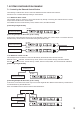
10.2. Output Volume Control • Closing the terminals for 250 ms or more causes an action to operate by 1 step*. * Select the variation from “1 dB step,” “3 dB step,” or “6 dB step” using the DP-SP3 PC Software. Max. 50 ms 200 ms Detects the leading edge. First volume control • Maintaining the terminals closed for 250 ms or more causes a 1-step action to repeat every 800 ms for 3 times, followed by 1-step action repeating every 200 ms. Opening the terminals stops these continuous actions.
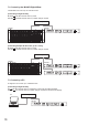
11. FIRMWARE VERSION INDICATION The DP-SP3’s firmware version can be confirmed by checking the lighting indicator status on the DP-SP3’s front panel. • Firmware Version Indication The DP-SP3’s firmware version is expressed as shown in the following example. Here, the individual numbers are denoted by A, B, and C. (Example) Ver. 1. 2. 4 A C B • How to check firmware version When the DP-SP3 is activated, the indicators on the front panel light for 3 seconds, indicating the figure of “A,” “B,” and “C.
12. INITIALIZING THE DP-SP3 Input level indicators Mute switches Output level indicators Power switch 1, 2 4 2, 3 Step 1. Turn off the power switch. Step 2. Turn on the power switch while continuously holding down the Mute switches 1, 2, and 5. All the front panel-mounted indicators light, then those except Input and Output level indicators go off. Step 3. When only the Input and Output level indicators light, release the Mute switches, then these indicators turn into flashing. Step 4.
13. INSTALLATION 13.1. Installation Precautions Be sure to leave the installation work (rack mounting) to a qualified installer. Rack CAUTION Power amplifier Blank panel DP-SP3 When installing the unit in an equipment rack, do not block the ventilation slots on the unit’s both sides and rear side. Doing so may cause heat to build up inside the unit and result in fire.
13.2. Mounting in a Rack CAUTION (When rack mounting screws are supplied) The supplied rack-mounting screws can be used for the TOA equipment rack only. Do not use them for other racks. When installing the unit in a rack other than that of TOA, be sure to use the screws with a diameter of over 5 mm (0.2”) and length of over 12 mm (0.47”) to mount the unit. Failure to do so may cause the unit to fall, resulting in personal injury.
14.2. Removable Terminal Plug Connection Notes • Avoid soldering stranded or shielded cable, as contact resistance may increase when the cable is tightened and the solder is crushed, possibly resulting in an excessive rise in joint temperatures. • When connecting 2 cables or a shielded cable to a single terminal, use a ferrule terminal with an insulation sleeve to crimp the cables because such cable conductors could become loose.
15.
DA Converter Preset Memory Signal Processing Section Equalizer/Filter Crossover Compressor Delay Matrix Crosspoint Gain Function Control Contact input Network Operating Temperature Operating Humidity Finish Dimensions Weight 24 bits 16 Parametric equalizer: 20 Hz − 20 kHz, ±15 dB, Q: 0.267 − 69.249 Filter: High-pass filter: 20 Hz − 20 kHz, 6 dB/oct, 12 dB/oct Low-pass filter: 20 Hz − 20 kHz, 6 dB/oct, 12 dB/oct Notch filter: 20 Hz − 20 kHz, Q: 8.651 − 69.249 All-pass filter: 20 Hz − 20 kHz, Q: 0.
17. DIMENSIONAL DIAGRAM Uint: mm (in) 482 (18.98) 31.6 (1.24) 6.1 (0.24) 44 (1.73) 465 (18.31) 288.7 (11.37) 280.3 (11.04) FCC REQUIREMENTS Note This equipment has been tested and found to comply with the limits for a Class A digital device, pursuant to Part 15 of the FCC Rules. These limits are designed to provide reasonable protection against harmful interference when the equipment is operated in a commercial environment.