
Instruction Manual

28
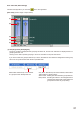
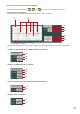
[Displayed in tabular form]
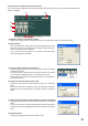
Clicking the Table indication button (No. 8) permits the lter control area to be displayed in tabular form.
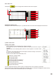
(1) Filter control area
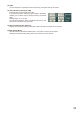
(2) Filter point
A circle on the lter control indicates the operable lter point.
A yellow circle indicates the selected lter point.
(When selected), (When not selected): High-pass filter
(When selected), (When not selected): Low-pass filter
(When selected), (When not selected): Gain control
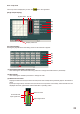
You can change the cut-off frequency of the selected lter point if you click and drag the low-pass or high-
pass lter point left and right.
To change the gain of the selected lter point, click and drag the gain control point up and down.
When a white circle is displayed on the right or left side of the lter point, if the white circle is clicked and
dragged up and down, the Q value of the selected lter point can be changed.
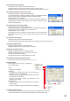
(3) Filter type indication button
Displays the type of lter of the selected lter point.
Clicking this button permits the lter type to be selected from the pull-down menu.
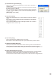
(4) Frequency indication button [Freq. (Hz)]
Displays the frequency of the selected lter point.
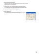
If you click this button, a dialog for frequency setting is displayed, enabling
you to set the frequency by directly entering a numerical value.
(Setting range: 20 – 20,000 Hz)
The Up and Down buttons located on the right side can also be used to
change the frequency setting.
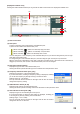
(5) Q/Q2 indication button [Q, Q2]
Displays the Q value of the selected lter point.
Clicking this button permits a setting value to be selected from the pull-down menu.
(6) Gain indication button [Gain (dB)]
Displays the gain of the selected gain control point.
If you click this button, a dialog for gain setting is displayed, enabling you
to set the gain by directly entering a numerical value.
(Setting range: –15 to +12 dB)
The Up and Down buttons located on the right side can also be used to
change the value in 0.5 dB units.
(1)
(3)
(4)
(5)
(8)
(9)
(10)