SOFTWARE INSTRUCTIONS Digital Speaker Processor DP-SP3 Thank you for purchasing TOA’s Digital Speaker Processor. Please carefully follow the instructions in this manual to ensure long, trouble-free use of your equipment.
TABLE OF CONTENTS 1. GENERAL DESCRIPTION OF THE DP-SP3 PC SOFTWARE ................................................................... 4 2. FEATURES ............................................................................................................. 4 3. RECOMMENDED PC REQUIREMENTS ............................................. 4 4. Installing the DP-SP3 PC Software .................................... 5 5. STARTING THE SOFTWARE .....................................................................
14. PRINTING THE SETTING DATA .......................................................... 68 15. Contact input terminal ............................................................... 69 15.1. General Description ............................................................................................ 15.2. Contact-In Setting Screen Description .............................................................. 15.3. Function Assignment to the Contact Inputs ....................................................
1. GENERAL DESCRIPTION OF THE DP-SP3 PC SOFTWARE This Software is designed to be used exclusively for setting parameters of acoustic signal processing functions such as the compressor and filter functions for the DP-SP3 Digital Speaker Processor. Install the Software program on a PC meeting the requirements below. 2. FEATURES • Up to four DP-SP3 units can be controlled from a single PC with this Software installed.
4. Installing the DP-SP3 PC Software Terminate all other application programs in operation before installation. Follow the procedures below to install. Step 1. Insert the supplied CD into the PC’s CD drive. Step 2. Open the CD drive from the “Explorer” or “My Computer.” The “English” folder, “Japanese” folder, and other contents are displayed. Step 3. Open the “English” folder. Step 4. Open the “DP-SP3_Software” folder. Step 5. Double-click the “setup.exe.” The following window is displayed. Step 6.
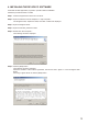
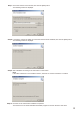
Step 7. Check the contents of the window, then click the [Next] button. The following window is displayed. Step 8. If necessary, change the folder into which the software will be installed, then click the [Next] button. The following window is displayed. Step 9. Start installation according to the instructions on the screen. Note If the .NET Framework is not installed in the PC, follow the on-screen instructions to install it. Step 10. Click the “Close” button after installation completion.
[Uninstalling the DP-SP3 PC Software] Step 1. Click the Start button on the PC’s desktop, and select [Setting The “Control Panel” window is displayed. Control Panel]. Step 2. Double-click the following icon. • Windows Vista and Windows 7 : [Programs and Features] • Windows XP : [Add or Remove Programs] The currently installed program will then be displayed. Step 3. Select “DP-SP3 GUI.” Step 4. Click the following button to uninstall the software.
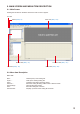
6. MAIN SCREEN AND MENU ITEM DESCRIPTION 6.1. Main Screen Starting the DP-SP3 PC Software causes the main screen to appear. Tool bar Flow view (See p. 18.) Menu (See p. 8.) Preset view (See p. 17.) Unit view (See p. 16.) Contents view (See p. 19.) Status bar (See p. 64.) 6.2. Menu Item Description 6.2.1. File New : Open... : Save : Save As... : Print Settings : Print : Print Preview : Creates (sets) a new setting file. Calls up the existing setting file. Overwrites the setting file being edited.
6.2.2. Edit Undo : Cancels the previous operation and returns to the original state. Repeat : Repeats processing previously performed. Cut : Initializes the setting value after copying the setting value of the designated box to the clipboard. Copy : Copies the setting value of the designated box to the clipboard. Paste : Pastes the clipboard data to the designated box. Initial value : Initializes the setting value of the box. Set Grouping : Performs the group setting of the box.
6.2.6. Remote Connect... : Disconnect : Connect the DP-SP3 to a PC for online processing. Disconnects the DP-SP3 from a PC for offline processing. Note While in offline state, the contents changed by a PC are not reflected on the settings of the DP-SP3. Bulk Transmission : Transmits data of the currently opened file to the unit. Bulk Receiving : Receives the DP-SP3’s internal date. Automatic Connection : Makes an automatic connection when the file is opened next time.
7. CONFIGURATION SETTINGS After starting up this PC Software, create the first unit, then perform configuration settings. In this PC Software, the data for which configuration settings are performed is referred to as “Unit.” 7.1. Creating the Unit Step 1. Click [Click to add first unit] (flow view) area on the main screen. The Unit Configuration setting screen is displayed. Step 2. Enter a unit name, then select the Unit ID. Up to 20 alphanumeric characters can be used.
Step 3. Click the [Next] button. Crossover combination screen is displayed. Note: To set the crossover function, proceed to Step 4. Otherwise proceed to Step 6. Step 4. Click the setting contents to perform the crossover combination settings. Setting status is displayed in the window on the right side of the screen.
Step 5. Click the [Next] button. The Crossover Slope screen is displayed. Setting status is displayed in the window on the right side of the screen. Note When using the template (See p. 15.), tick “Template” box and click the [Click Here] button on its right. A dialog box for selecting the file is then displayed. If you select the file and click the [Finish] button, the signal flow is displayed. Step 6. Check to ensure that the setting is correct and click the [Finish] button. The signal flow is displayed.
Step 7. Set the Input PAD. 7-1. Select “Unit Input Pad Settings” from the menu when the communication with the DP-SP3 unit is disconnected. The Input PAD Setting screen is displayed. 7-2. Set each input sensitivity of Inputs 1 and 2, then click the [OK] button. PAD ON: +4 dB* PAD OFF: –10 dB* * 0 dB = 0.775 V Note Input PAD setting can be operated only when connection to the DP-SP3 unit is not established.
7.2. Deleting the Unit The unit configuration already created can be deleted only when the PC is not in communication with the DPSP3. Select the unit to be deleted in the unit view or flow view. Select [Unit Delete Unit] from the menu to display a dialog for confirmation. Clicking the OK button deletes the unit. 7.3. Changing the Crossover Combinations The configuration crossover combination already created can be changed only when the PC is not in communication with the DP-SP3.
8. UNIT OPERATION 8.1. Unit View The Unit View is located at the upper left of the main screen. It displays up to 4 units in a list-view or in a tree-view style, which can be switched by clicking the tab below. Display view style Tab name List-view Unit List Tree-view Unit Tree Unit View 8.1.1. List view Displays the signal processing images of the unit in a reduced size.
8.2. Preset View The preset view is located at the lower left of the main screen. Preset view It shows the preset memory names and the preset numbers being currently selected. It is also possible to change, store, and compare the preset data. Preset memory list Change button Store button Compare button • The currently selected preset memory number is displayed in bold in the preset memory list. • To recall a preset memory, click the corresponding preset memory name and click the [Change] button.
8.3. Flow View The flow view displays the signal processing image indicated by a signal flow chart consisting of the signal processing functional boxes and input-to-output lines connected between them. Flow view Unit name (See p. 16.) Crossover (Xover) (See p. 27.) : Low-pass filter : High-pass filter : Band-pass filter Delay (See p. 31.) Attenuator (See p. 33.) Mute*1 Signal indicator*2 (High-pass filter + low-pass filter) Gain (See p. 21.) Compressor (See p. 23.) Filter (See p. 25.) Matrix (See p.
*2 The display of the signal indicator changes depending on the signal levels at the input and output while the PC is in communication with the DP-SP3. LEVEL D LEVEL B LEVEL A LEVEL C • The indicator LEVEL A indicates the signal level immediately after analog-to-digital conversion obtained from the unit. • The indicator LEVEL B indicates the signal level obtained by adding the input gain value to the LEVEL A signal level.
8.4.1. Matrix view Clicking the Matrix box in the signal flow causes the Matrix view to be displayed. Matrix control Numerical value indication button Fader Level setting button Example of numerical display • A circle mark in the matrix control column shows input/output routing. • The Matrix control turns on and off as it is double-clicked. • A black, thicker frame on the Matrix control shows the selected matrix point.
8.4.2. Gain view (Gain settings) The Gain view appears if you click the box in the signal flow. [Gain view] (Former stage of input section) (1) (2) (3) (4) (5) (1) Grouping button [Grouping No.] The group number is displayed when grouping has been set, and the “Off” indication is displayed when no grouping has been set. Clicking on this button permits grouping to be set or cancelled on the pull-down menu.
(2) Fader You can change the signal level of each channel by moving this fader up and down. (3) Gain indication button [Gain (dB)] Indicates each channel signal level in dB. If you press this button, a dialog for gain setting is displayed, enabling you to set the gain by directly entering a numerical value. (Setting range: –∞ to +12 dB) You can also change the gain in 0.5 dB units with the Up and Down buttons located on the right side. (4) Reverse polarity button [Polarity] Displays each channel’s polarity.
8.4.3. Comp view The Comp view is displayed if you click the box in the signal flow. [Single output display] (1) Red mark (2) (3) (4) (5) (6) (7) (8) Display switch tab [All output display] Clicking the [All] tab causes the setting screen for all channels to appear. (4) (5) (6) (7) (8) (1) Threshold handle (Red indication mark) Click and drag this threshold handle along a tilt line to change the threshold level. (Threshold). (2) Ratio handle Click and drag this handle up and down to change the ratio.
(4) Threshold button [Threshold (dB)] Displays the compression threshold level for each channel by means of numerical values. The Up and Down buttons located on the right side can be used to change the threshold level in 1 dB units. Also, if you press this button, a dialog for threshold level setting is displayed as shown at right, enabling you to set the level by directly entering a numerical value.
8.4.4. Filter view Clicking the (1) box in the signal flow causes the Filter view to appear. (2) (3) (4) (5) (6) (7) (8) (9) (10) (11) [Displayed in tabular form] Clicking the Table indication button (No. 11) permits the filter control area to be displayed in tabular form. (1) (3) (4) (5) (6) (7) (8) (9) (10) (11) (1) Filter control area (2) Filter point symbol Select the filter point from the filter point symbol as required.
(3) Filter type indication button Indicates the type of filter of the selected filter point. Click this button to select the type of filter from the pull-down menu. Selecting “Through” causes the circle to disappear from the filter control area. (4) Frequency indication button [Freq. (Hz)] Displays the frequency of the selected filter point. If you click this button, a dialog for frequency setting is displayed, enabling you to set the frequency by directly entering a numerical value.
8.4.5. Xover view (Crossover function settings) The Xover View is displayed if the , , or box of Xover is clicked in the signal flow. [Crossover function settings ] The screen of the [Xover] tab is first displayed if the box of Xover is clicked. (2) (1) (3) (4) (5) (8) (9) (10) The indication displayed at the upper right of the screen changes depending on the type of selected filter.
[Displayed in tabular form] Clicking the Table indication button (No. 8) permits the filter control area to be displayed in tabular form. (1) (3) (4) (5) (8) (9) (10) (1) Filter control area (2) Filter point A circle on the filter control indicates the operable filter point. A yellow circle indicates the selected filter point.
(7) Reverse polarity button [Polarity] Displays the polarity of the selected filter point when the gain control is selected. Press this button to reverse the polarity. (8) Table indication button The filter control area is displayed in tabular form if this button is clicked. To return the screen to the original graphical display, click this button again. (9) Frequency response indication button Used to show or hide the Response View (See p. 34.
[Time correction settings between Xover boxes] If you click the [Driver Alignment] of the Display Switch tab, the setting screen for time correction between Xover boxes is displayed. (1) (2) (3) (4) (5) (6) (1) Minimum variation unit selection button Selects the minimum units of the delay time that can be changed with the Up and Down buttons.
8.4.6. Delay view (Delay function settings) If you click the box in the signal flow, the Delay View is displayed. (1) (2) (3) (4) (5) (6) (1) Minimum variation unit selection button Selects the minimum units of the delay time that can be changed with the Up and Down buttons. (2) Option button If you click this button, a delay option dialog is displayed and you can select the unit of distance displayed on the delay distance indication button from meters, inches, and feet.
(4) Delay time indication button [Time (ms)] Displays the delay time in each channel by means of a numerical value. If you press this button, a dialog for delay time setting is displayed, enabling you to set the delay time by directly entering a numerical value. (5) Delay distance indication button [Distance (meters/inches/feet)] Displays the delay distance in each channel by means of a numerical value.
8.4.7. ATT view If you click the box in the signal flow, the ATT View is displayed. (1) (2) (3) (4) (1) Grouping button [Grouping No.] The group number is displayed when grouping has been set, and the “Off” indication is displayed when no grouping has been set. Clicking on this button permits grouping to be set or cancelled on the pull-down menu.
8.5. Response view Select [View Response View] from the menu or click the Frequency response indication button on the Filter (See p. 25.), or Xover View (See p. 27.) to show or hide the Response View. The Response View can display the Output response and Xover response. The Xover Response View is displayed only when the filter box is selected in the flow view. Response View 8.5.1. Output response view Displays an overall response from input to output.
(4) Input selection button [Output 1 − 6] Click this button to select either ON or OFF of response display of each output channel, or input channel from the pull-down menu. (5) Color change button If this button is clicked, a dialog for color setting is displayed, permitting the display colors of response curves of each channel to be changed. 8.5.2. Xover response view Displays crossover and filter response curves. Displays each channel response, as well as their added overall response.
(2) Scale change button If you click this button, a dialog for scale setting is then displayed and the graph scale of the response control can be changed. (3) Measuring data import button You can simulate crossover settings of the multi-way speaker by importing measuring data obtained by other measuring software. Click this button to select the target channel from the pull-down menu. (4) Measuring data calibration button Click this button to display a dialog for response display calibration.
8.6. Preset Memory Settings There are 16 preset memory patterns. You can freely recall them or write data into them. 8.6.1. Recalling the preset memory Select [Preset Change Preset 1 − 16] from the menu. It is also possible to recall from the Preset View. (See p. 17.) 8.6.2. Writing data into the preset memory Store Preset 1 − 16] from the menu. Select [Preset It is also possible to write on the Preset View. (See p. 17.
8.6.3. Preset Memory settings at power-on Power On” from the menu, then select “Resume,” Select “Preset “Last Preset,” or “Preset 1 to 16” (Preset number). Resume: Activates the DP-SP3 in the state just before poweroff. Last Preset: Activates the DP-SP3 with the Preset memory setting data selected just before power-off. Preset 1 – 16: Activates the DP-SP3 with the setting data of the selected Preset memory. After completion of the setting, establish connection with the DP-SP3 (See p. 53.
8.6.5. Preset memory switching host settings Preset memory interlock function allows the unit’s Preset memory to be switched synchronously when the Preset memory of the M-864D or other DP-SP3 unit (Master device) is switched. Step 1. Select “Preset Switching Host...” from the menu. The Preset Switching screen is displayed. Step 2. Tick the “Enable Preset Switching” check box, then set the IP address of the Preset interlock origin device (M-864D or DPSP3 that functions as a Master).
8.7. Level Monitor View The Level Monitor View window permits monitoring of the unit’s input and output signal levels while the PC is in communication with the DP-SP3. • Levels of up to 4 units can be displayed. • Displays the levels of 2 inputs and 6 outputs for each unit. • Displays the value of LEVEL A (See p. 19.) of the signal indicator in the Flow view as input level. • Displays the value of LEVEL D (See p. 19.) of the signal indicator in the Flow view as output level.
8.8. Mute View It is possible to mute all or individual DP-SP3’s outputs simultaneously by way of communication connection established using the DP-SP3 PC Software. 8.8.1. Displaying a Mute view Mute view can be displayed using either of the following two methods. [Docking display] Select [View Mute View Mute ON Docking] from the menu.
[Floating display] Select [View Mute View Mute ON Floating] from the menu. Mute OFF 8.8.2. Mute view operation The Mute view can be operated only while online with the DP-SP3 unit. Mute ON/OFF data obtained through the Mute switch operation on the DP-SP3 unit’s front panel is reflected in this view. Also, the setting and reset data obtained through operations on the Mute view are reflected to the indication statuses of the unit’s front panel-mounted output level indicators.
9. Using The preset G The Preset G, a memory that is different and independent from the Preset memories 1 through 16, can be shared by these Preset memories. By setting the parameters to be shared as Preset G, they can be commonly used by multiple Preset memories. Each Preset memory retains its own original parameters. Cancelling the Preset G setting causes the original parameters to be enabled. When controlling multiple units, parameters set in the Preset G are simultaneously set to their all preset G.
Step 2. Click “Option Preset G enable settings” from the menu bar. The “Enable Preset G” screen is displayed. Step 3. Select the Preset memory that intends to use the common parameters, then place checkmarks in the parameter boxes. To place checkmarks collectively throughout all Preset memories, perform setting on the screen displayed when the ALL tab is clicked.
(Example when a checkmark is placed in the Preset 2’s Gain box) (Example when checkmarks are placed in the Preset 3’s Filter and Delay boxes) Step 4. Click the “OK” button on the “Enable Preset G” screen. Setting is completed, and the screen returns to the display in Step 1. The boxes corresponding to the set parameters are displayed in orange. Step 5.
10. COMMUNICATIONS This PC Software enables communications between a PC and the DP-SP3 unit via TCP/IP. 10.1. Method to Set Communications with the DP-SP3 Unit 10.1.1. Communication setting procedures between a PC and the DP-SP3 unit Step 1. Select [Remote Connection Settings] from the menu to display the “Check IP Settings” screen. The screen below shows that 2 devices are detected as connectable devices.
[When the communication setting is not configured correctly] When the network address of a PC running this PC Software and that of the DP-SP3 unit are not identical, such device is listed in the “Other Network Devices” field as shown below, so that this PC Software cannot operate this DP-SP3. When IP addresses of the multiple DP-SP3 units are duplicated, such devices are listed in “Unconnectable Devices,” so that this PC Software cannot operate them.
[Correcting the communication setting] Retry setting with the procedures below. (1) Select the device with an incorrect or duplicated IP address and click the [Modify IP Setting] button, then the “IP Setting” screen is displayed. Enter the correct IP address. Note: In this case, the network address of the PC running this PC Software is mandatorily designated. Note: To perform default gate way setting, tick the [Enable edit of the “Default Gateway”] checkbox.
The modified IP setting is sent to the DP-SP3 unit, thereby being reflected in the DP-SP3. Step 2. When performing connection to the DP-SP3 unit via router, click the [Add] button, then manually set the connected device.
Step 3. If there is any DP-SP3 unit to be removed from the connected device list, select such DP-SP3 unit from the list, then click the [Remove] button. Step 4. Click the [Next] button. The “Check Firmware Version” screen is displayed. If all connected devices are in controllable state, the screen below will appear.
(1) If the DP-SP3 unit uncontrollable due to its firmware version problem is found, such unit is shown on the “Uncontrollable Devices” list. To make it controllable, click the [Update Firmware Version] button. (2) Click the [Next] button in the “Check Firmware Version” screen, then the “Check Unit ID” screen is displayed. The screen below shows that all connected devices are in controllable state.
Step 5. To change ID, click the [Modify Unit ID] button. All the DP-SP3 units’ ID is factory-preset to “1.” In this case, the Unit ID setting screen is displayed as shown below. Step 6. Click the [Finish] button.
10.1.2. Communication procedures between a PC and the DP-SP3 unit Step 1. Select one of the followings from the menu, and detect the connected device. • [Remote Connect...]: Set the transfer direction when the setting data between a PC and the DP-SP3 unit are different. • [Remote Bulk Transmission]: Transmits all setting data from a PC to the DP-SP3 unit. • [Remote Bulk Receiving]: Transmits all setting data from the DP-SP3 unit to a PC.
Step 2. To transmit the setting data, select [PC>>Unit] or [Unit>>PC], then click the [Update] button. Data transfer starts. Step 3. After completion of data transfer, click the [Complete] button. To end communication, select [Remote Disconnect] from the menu.
11. SPEAKER PARAMETER SETTINGS USING A WEB BROWSER Operations shown below can be performed using a Web browser. • Preset number selection • Crossover settings • Matrix settings 11.1. Speaker Parameter Settings 11.1.1. Displaying a Web browser’s top page Enter the IP address of the DP-SP3 for which speaker parameters are to be set in the URL input field of the Web browser. The top screen for the DP-SP3 Speaker parameter settings is displayed.
11.1.2. Changing the Preset number Step 1. Click on the “Preset No. Setting” text on the Web browser’s top page. Preset No. Setting screen is displayed. Step 2. Select the Preset No. to be changed to. Step 3. Click the [Apply] button. 3 2 Changed settings are reflected in the DPSP3 unit. Note Clicking on the “Top” text returns to the top page.
11.1.3. Xover combination settings Crossover settings can be performed by selecting the preset Speaker parameters in the DP-SP3. Step 1. Click on the “Xover Combination Setting” text on the Web browser’s top page. The Xover Combination Setting screen is displayed. 2 Step 2. Set the Crossover combinations of the desired channel. Select “Single,” “2-Way,” or “3-way.” Step 3. Select the speaker to be used from the “Template” list. Crossover combinations are set for individual channels.
11.1.4. Matrix setting Step 1. Click on the “Matrix Setting” text on the Web browser’s top page. The Matrix Setting screen is displayed. Step 2. Set On or Off to the desired cross point of the input and output. Step 3. Click the [Store] button. 2 3 Changed settings are reflected in the DPSP3 unit. Note Clicking on the “Top” text returns to the top page.
11.1.5. Confirming the changed data To confirm the changed data, establish connection with the DP-SP3 unit (See p. 53.) using the PC software. Note JavaScript may be disabled depending on the Web browser’s setting. When the connection is established under such conditions, the screen as shown below is displayed. Change the Web browser settings, then connect the DP-SP3 unit using the PC Software again.
11.1.6. Creating the Speaker preset data by yourself It is possible to save the Crossover template file (See p. 15) created using the PC Software into the unit as the custom template data. Note When saving the Crossover template file, be sure to name the title in addition to the file name. The title name of the Crossover template file becomes the speaker preset data name. There is no limit to the type of input characters of the title name. [Adding the custom template] Step 1.
The Add Parameter completed screen is displayed. Step 4. Check that the Parameter has been added. You can confirm the newly added parameter on the Custom Parameter Setting screen that appears by clicking on the “Custom Parameter Setting” text. [Deliting the custom template] Step 1. Click on the “Custom Parameter Setting” text on the Web browser’s top page. The Custom Parameter Setting screen is displayed. Step 2. Click the [Remove] button of the parameter to be deleted.
The Remove Parameter screen is displayed. Step 3. Click the [Apply] button. The Remove Parameter completed screen is displayed. Step 4. Check that the Parameter has been deleted. You can confirm that the designated Parameter has been deleted on the Custom Parameter Setting screen that appears by clicking on the “Custom Parameter Setting” text.
12. SECURITY SETTINGS The DP-SP3 PC Software features the following 2 different user levels that can be used in the Restriction Settings explained in the next section. • Administrator: If the user level is not set, Administrator is automatically selected for the level. Logging on as an administrator on the logon screen also sets the user level to Administrator. • Operator: If you do not log on as an administrator on the logon screen, the user level is set to Operator. 12.1. Enabling the User Level Step 1.
12.2. Logging on When the User Level is Enabled The following logon screen is displayed when the data file is opened after the user level has been enabled. When logging on as an administrator, enter a set password and click the [OK] button. If a different method than this is used to close the logon screen, the user level is logged on as an operator. The level logged on is displayed on the right side of the status bar located at the lower part of the main screen.
12.3. Restriction Settings 12.3.1. Operations that can be restricted • Creation and deletion of the unit and input/output change • Crossover combination change • Grouping change • Name change • Storage in preset memory • Parameter change for each box 12.3.2. Performing restricted settings Step 1. Select [Option Security Settings] from the menu. The Security Settings dialog is displayed. Step 2. Select the restriction level from the pull-down menu of each item of Restriction settings.
You can set 4 different levels of restrictions for each item. Off Both administrators and operators can change the item and Restriction settings. Mid Administrators can change the item and Restriction settings. Operators cannot change the item and Restriction settings. Low Administrators can change the item and Restriction settings. Operators cannot change the item, but can change Restriction settings. High Administrators cannot change the item, but can change Restriction settings.
Step 3. Perform restriction setting of parameter change for each box. Select [Edit Box Write Protect...] from the menu while the box is selected in the flow view. Example: When performing restriction setting of the filter box 13. DP-SP3’S MUTE SWITCH LOCK ON/OFF SETTING The DP-SP3 unit’s front panel-mounted Mute switch operations can be disabled. Step 1. Place the PC in communicate with the DP-SP3 of which Mute switch you want to lock. Step 2. Select “Option Front Lock On/Off On or Off” from the menu.
14. PRINTING THE SETTING DATA The setting data of the file being edited can be printed. Step 1. Select [File Print] from the menu. Dialog for print area is displayed. Step 2. Set the unit to be printed. Select “Created” to print the created data of all the units. To print the data of the arbitrary units, select “Selected,” then click on the button of the units to be printed. Step 3. Set the preset to be printed. Select [All] when printing all the data stored in 16 presets.
15. Contact input terminal 15.1. General Description The DP-SP3 unit is equipped with 4 contact input terminals that permit preset memory change, output volume control, and output mute control to be performed. Present memory change function has been assigned by default; Pins 1 through 4 are assigned to Preset Nos. 1 through 4, respectively. Preset Nos. 1 through 4 can be individually recalled by shorting the terminals 1 through 4 to terminal C.
(5) Channel Select Select the target channel of which control output volume and output mute are to be controlled. (6) [Disable] button/ [Enable] button Clicking the [Disable] button disables control from the Contact input, turning into [Enable] button. Preset number of the controls performed before clicking the [Disable] button is retained, but both output volume and output mute controls are cleared. To control again, click the [Enable] button.
15.3. Function Assignment to the Contact Inputs 15.3.1. Preset memory change [When in Direct mode] Step 1. Set the Mode to [Direct] and Function to [Preset]. Step 2. Click the Parameter button, then select the Preset number from the pull-down menu. [When in Binary mode] Note: When changing Preset in Binary mode, either output volume control or output mute control can be assigned to other Pins.
15.3.2. Output volume control Gives an offset value to the value set to the output attenuator. Notes • Output volume control can be performed only to the DP-SP3 unit targeted by the contact input. • Group the output channels, then perform controls in groups. • The channels belonging to the same group are equal in the obtained offset value but not in the output attenuator value. • It is not possible to assign the same channel to 2 or more groups.
15.3.3. Output mute control Assign the Mute ON/OFF function to the Pin. Notes • Output mute control is only available to the DP-SP3 unit targeted by the contact input. • Group the output channels, then perform controls in groups. • When “Pulse” is selected for the control method, even if the unit’s power is switched off, the output mute state can be recalled when the power is switched on again.
15.4. List of Functions Assignable to Pins Functions assignable to Pins 1 through 4 are listed below.
URL: http://www.toa.